Polygon To Line
Data Description
Input and Output Relationships

Input and Output Relationships for Polygon to Line
Description:
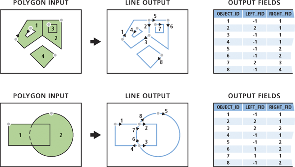
If the Identify and Store Polygon Neighborhood Information checkbox is selected, the tool will analyze polygon neighborhood relationships. When converting boundaries to lines, intersecting or common segments will be considered, and two new fields,
LEFT_FIDandRIGHT_FID, will be added to the output feature class. These fields will be set to the IDs of the polygons to the left and right of each output line, respectively. The attributes of the input features will not be retained in the output feature class. The following scenarios illustrate the process and output in more detail:- In polygon geometry, outer boundaries are always stored in a clockwise direction. Holes within the polygon are stored in a counterclockwise direction. Therefore, if neither the external boundary (outside) nor the hole boundary (inside) has neighboring points, the
LEFT_FIDof the generated line will be -1, while theRIGHT_FIDwill be set to the polygon feature ID. - If a polygon contains another polygon, a clockwise output line will be generated to represent the common boundary, with
LEFT_FIDset to the external polygon feature ID andRIGHT_FIDset to the internal polygon feature ID. - If two polygons share a boundary, an output line representing this common segment will be generated. The direction of the line can be arbitrary;
LEFT_FIDandRIGHT_FIDwill be set to the respective feature IDs of the polygons on either side of the line. - If a polygon overlaps another polygon, two output lines will be created to represent each intersecting boundary: the first line will represent the outer boundary of one of the overlapping polygons, with
LEFT_FIDset to the intersecting polygon's ID andRIGHT_FIDset to its own feature ID; the second line, oriented in the reverse direction, will split the other polygon, withLEFT_FIDandRIGHT_FIDboth set to the ID of the second polygon. - Multipart polygons in the input will not be preserved; the output lines will be single-part.
- In polygon geometry, outer boundaries are always stored in a clockwise direction. Holes within the polygon are stored in a counterclockwise direction. Therefore, if neither the external boundary (outside) nor the hole boundary (inside) has neighboring points, the
If the Identify and Store Polygon Neighborhood Information checkbox is not selected, polygon neighborhood relationships will be ignored. The boundaries of each input polygon will be written as closed line features. Multipart polygons will become multipart lines in the output. The attributes of the input features will be retained in the output feature class, with a new field
ORIG_FIDadded and set to the ID of each line’s input feature.
Steps
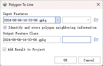
Find the Polygon To Line tool in the toolbox and double-click to open the tool window.

Polygon To Line
Parameter Description:
- Input Features: The input features must be polygons.
- Identify and store polygon neighboring information (Optional): Specifies whether to identify and store polygon neighborhood information.
- Checked - Identifies polygon neighborhood relationships and stores these relationships in the output. If different segments of a polygon share boundaries with different polygons, these boundaries will be split into unique shared line segments, with the FID values of the two neighboring polygons stored in the output, as illustrated. This is the default setting.
- Unchecked - Ignores polygon neighborhood relationships; each polygon boundary will be converted into line features, and the original polygon FID will be stored in the output.
- Output Feature Class: The output line feature class.
- Add Result to Project: This option is only applicable if the output feature class result is being written to a gpkg database in the project. Checking this will automatically create a layer for the result data and add it to the project.