Graphic Buffer
Function Description: Creates buffer polygons around input features to a specified distance. A number of cartographic shapes are available for buffer ends (caps) and corners (joins) when the buffer is generated around the feature.
Data Description
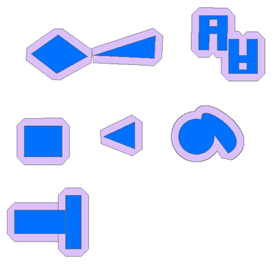
Input and Output Relationship

Input and Output Relationship for Graphic Buffer
Notes:
Note: This tool's output is intended only for cartographic display and should not be used for further analysis, as it may result in erroneous outcomes.
Input features can be points, lines, or polygons. The options for buffer endpoints (ends) and corners (joins) depend on the type of input features.
- Endpoint types - available for points and lines only.
- Join types - available for polygons and lines only.
The output feature class will include a
BUFF_DISTfield, which contains the buffer distance used for each feature (in linear units of the input feature's coordinate system). If aBUFF_DISTfield exists in the input, its value will be overwritten in the output.The output feature class will include an
ORIG_FIDfield, which contains the feature ID of the input feature for which the buffer was created. If anORIG_FIDfield exists in the input, its value will be overwritten in the output.For buffering polygon features, a negative buffer distance can be used to create a buffer inside the polygon. A negative buffer distance will shrink the polygon boundary inward by the specified distance.
Note: If the negative buffer distance is large enough to reduce the polygon to non-existence, empty geometry will be generated. A warning message will appear, and no empty geometries will be written to the output feature class.
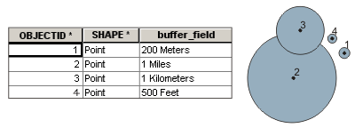
When using a field from the input to obtain buffer distances, the field's values can be either a number (e.g., 5) or a number with a valid linear unit (e.g., 5 kilometers). If the field value is a number, the distance is assumed to be in the linear unit of the input's spatial reference (unless the input uses a geographic coordinate system, in which case the value is in meters). If the specified linear unit in the field value is invalid or unrecognized, the input's spatial reference linear unit will be used by default.

Example of Using a Field to Obtain Buffer Distance
Steps
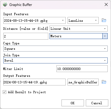
Locate the Toolbox -> Vector Tools -> Overlay Analysis -> Graphic Buffer tool, and double-click to open the tool window.

Graphic Buffer
Parameter Description:
- Input Features: The point, line, or polygon features to be buffered.
- Distance [value or field]: The distance to buffer around the input features. This distance can be specified as a linear value or as a field in the input features containing the buffering distance for each feature. If no linear unit is specified or if "unknown" is entered, the linear unit of the input feature's spatial reference will be used.
- End Type (Optional): Specifies the end type of the input features to be buffered. This parameter only applies to points and polygons.
- Square—The output buffer around the end of the input segment will have a square end. This is the default setting.
- Butt—The end of the output buffer will be perpendicular to the end of the input segment.
- Round—The output buffer around the end of the input segment will have a round end.
- Join Type (Optional): The shape of the buffer at the corners where two line segments join. This parameter only applies to lines and polygons.
- Beveled—Generates a square or angled shape around the corner of the output buffer. For example, a square input polygon will have a square buffer. This is the default setting.
- Miter—The output buffer at the inner corner will be square, while the outer corner, perpendicular to the farthest point of the corner, will be trimmed.
- Round—The output buffer at the inner corner will be square, while the outer corner will be round.
- Miter Limit (Optional): When line segments intersect at acute angles and the Beveled type is specified, this parameter controls how the acute angle of the buffer output gradually becomes a point. In some cases, using the Beveled type can result in very large external angles at the line connections, potentially extending the corner points beyond expected limits.
- Output Features: The feature class that will contain the buffered output.
- Add Results to Project: This option is only effective when outputting the feature class results to a geodatabase in the project. When checked, a layer for the result data will be automatically created and added to the project.