Strip Adjustment
Parameter Description
1.Click Strip Adjustment![]() After pressing the button, a pop-up box pops up:
After pressing the button, a pop-up box pops up:
- Project Data: Supports setting reference projects and registration projects participating in the adjustment, and supports setting point clouds, trajectories, and control points for each project.
- Adjustment Parameters: Supports setting the parameters of trajectory segmentation, segmentation registration, and SPLIEN adjustment steps.
2.Project Data
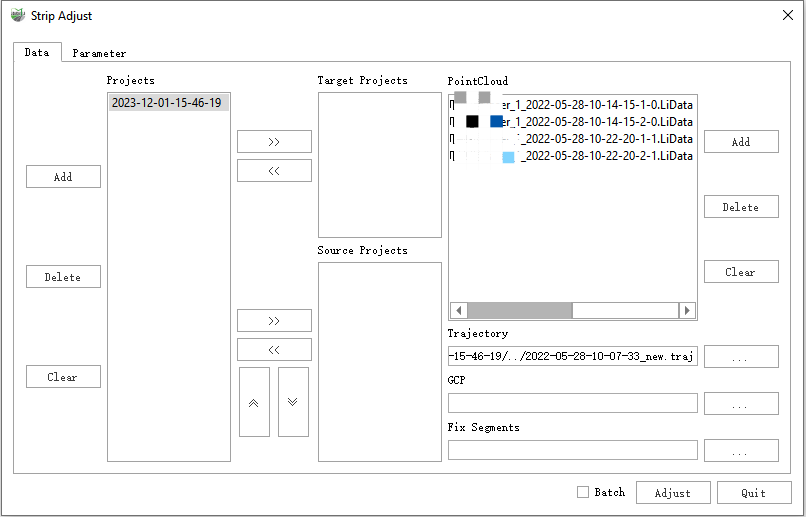
- Add Project: Add project files (.LiStreet, .LiMMP) from outside.
- Delete Project: Delete the added project.
- Clear Project: Clear all projects.
- Add target project: Select one in the project bar and click Add to target project.
- Remove Target Project: Remove the added project from the target project to the project list.
- Add Matching Project: Select one in the project bar and click Add to Matching Project.
- Remove Matching Projects: Remove a project from the matching project column to the project list.
- Move Matching Project Up: Move the selected registration project down one place to adjust the order of the registration projects. It is sorted by the acquisition time or the location of the acquisition area, and the adjustment calculation will be performed in the order of the projects.
- Move Matching Projects Down: Move the selected registration project up one place to adjust the registration project sequence. It is sorted by the acquisition time or the location of the acquisition area, and the adjustment calculation will be performed according to the project order.
- Add Point Cloud: Select any target/matching project and add point cloud file.
- Delete Point Cloud: Select any target/matching project, and delete a certain segment/several segments of the point cloud file.
- Clear Point Cloud: Select any target/matching project, clear all point cloud files in the project and set again.
- Select Track: Select any target/matching project and reset the track file.
- GCP: Select any target/matching project, import the GCP control point file corresponding to the current project, and the file will be saved and generated by saving the puncture points through the Control Point Correction function.
- Fixed trajectory segmentation: Select any target/matching project, import the trajectory segment file corresponding to the current project, and this file is generated by selecting part of the trajectory through the Trajectory Segmentation function. The selected trajectory indicates that these data will not be processed during stitching.
3.Adjustment Parameters
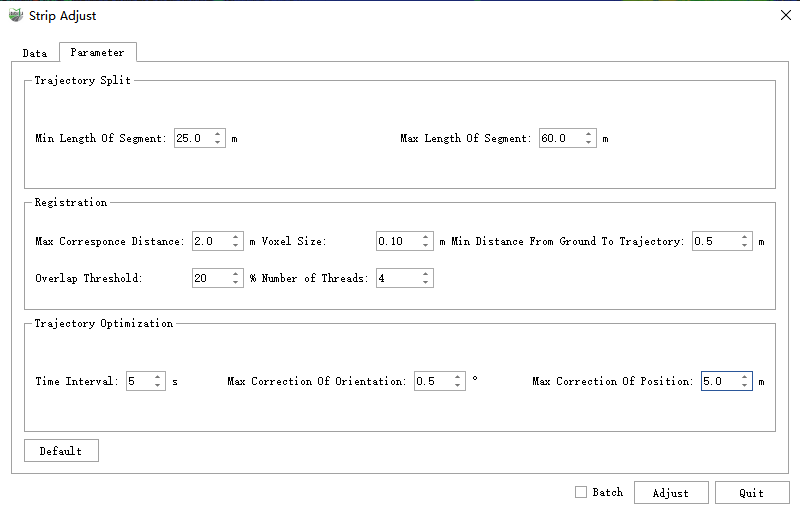
Trajectory Split:
- Min Length of Segment: The minimum length of the track segment result. It is recommended to set the default value.
- Max Length of Segment: The maximum length of the track segment result. It is recommended to set the default value.
- It can be adjusted according to the size of the collection area, the open area can be appropriately enlarged, and the shaded area should be reduced. Segmented point cloud is based on trajectory segmentation and provides matching point cloud for segment matching.
Registration:
- Max Correspond Distance: Matched pairs whose distance is greater than this value do not participate in the adjustment. It is recommended to set the default value.
- Voxel Size:In the matching process, set the voxelization sampling interval for matching point clouds. Setting it too large may cause the disappearance of key points, while setting it too small results in a large computational load. It is recommended to use the default settings.
- Min Distance from Ground to Trajectory: Ground points with a distance from the track height less than this value will be filtered. It is recommended to set the default value.
- Overlap Threshold: Matching pairs with overlap less than the threshold will be filtered. It is recommended to set the default value.
- Number of Threads: Match the number of threads, which is related to the computer configuration. It is recommended to follow the default. Segment matching performs relative splicing based on the revisited endpoint cloud, which provides matching constraint information for the subsequent SPLINE overall adjustment optimization, which directly affects the final splicing effect.
SpLine Optimization:
- Time Interval: SPLINE node time interval, the smaller the interval, the finer the pose correction and the greater the calculation amount. It is recommended to set the default value.
- Max Correction of Position: The maximum correction amount of SPLINE node position. It is recommended to set the default value.
- Max Correction of Posture: The SPLINE overall adjustment takes the trajectory pose corresponding to the SPLINE node as the basic adjustment unit, and adjusts the trajectory pose correction based on the SPLINE assumption to perform adjustment optimization to achieve the corrected trajectory pose splicing point cloud and guarantee the corrected trajectory pose smooth and specific effects. The maximum amount of correction for the attitude of SPLINE nodes. It is recommended to set the default value.
Single Project Strip Adjust
1.Through New Project or directly Open ligeo Project method, open the vehicle engineering data to be optimized, and it is recommended to configure the image information here.
2.Click the ![]() function button, in the setting of the air belt splicing project, move the current project to the matching project. If internal splicing of control point parameters is required, you need to pass Control Point Correction in advance to puncture the control point and save it as an .xml file, and then load the modified file into the control point file setting of the current project of the air belt splicing.
function button, in the setting of the air belt splicing project, move the current project to the matching project. If internal splicing of control point parameters is required, you need to pass Control Point Correction in advance to puncture the control point and save it as an .xml file, and then load the modified file into the control point file setting of the current project of the air belt splicing.
3.Click the Splicing button to activate the splicing function. The air belt splicing will not recreate the original data. Under the folder where the current project is located, a new project and folder with "current project name-adjust" will be generated. The spliced point cloud, trajectory and other data are stored in "\adjust\optimize_result" path.
4.If there are multiple sets of single projects that need to be spliced, you only need to add all single projects to the project list by adding projects, and then move them into matching projects, and check the batch check box processing at the top and bottom. The internal adjustment operation is performed on each group of projects in sequence. The adjusted results of each group of projects are in the adjust folder under the folder where the respective projects are located.
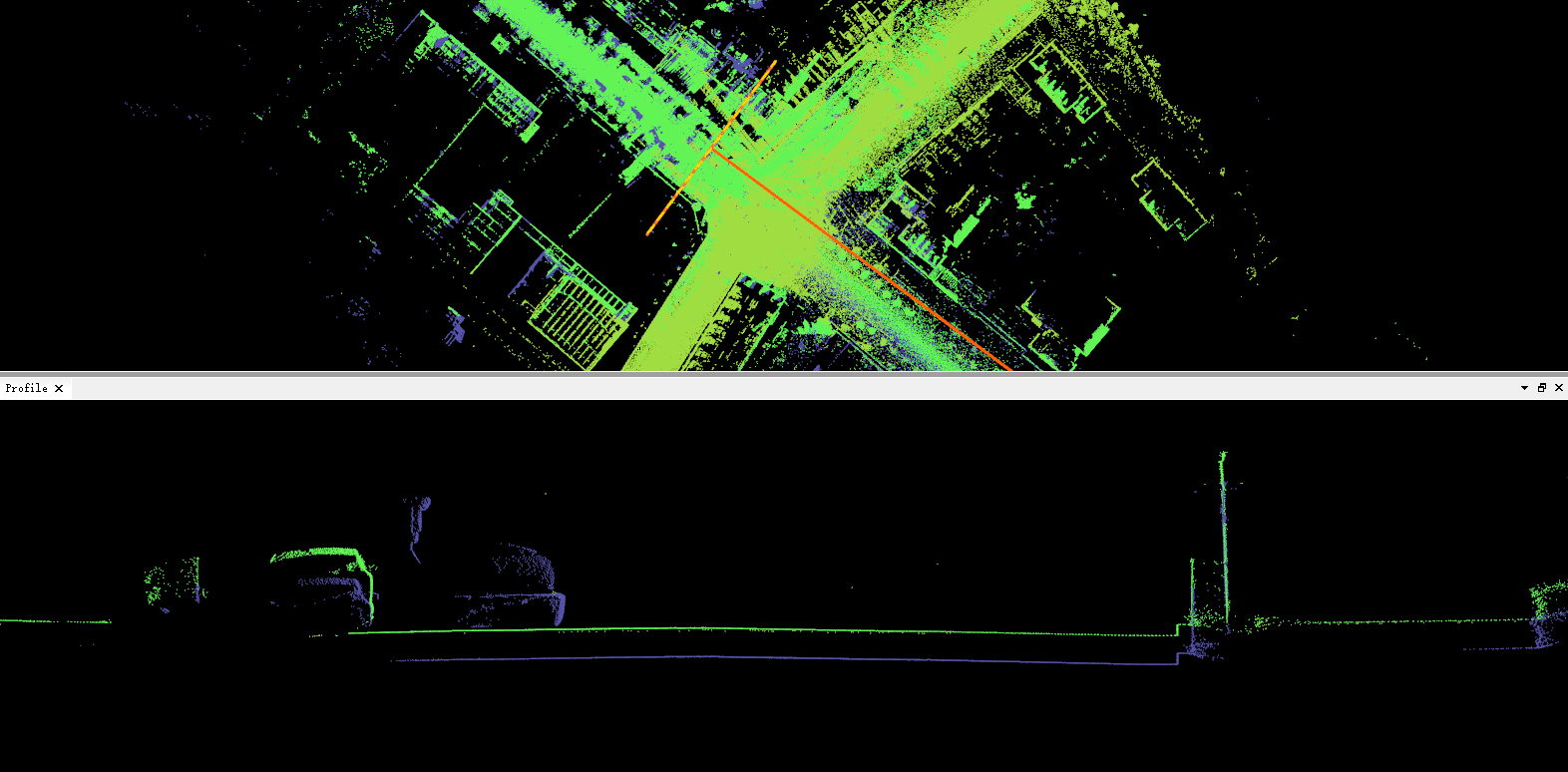
Before the single-engineering air belt splicing
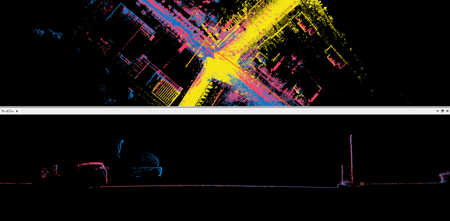
After the single-engineering air belt splicing
Multi-project Strip Adjust
1.Assuming that there are four groups of ABCD projects, the AB, BC and CD projects have a certain range of public areas respectively. Due to the unobstructed ground and other reasons, the point clouds of the two projects with the same name do not completely overlap, and there are certain layers, and A project has participated in single project splicing through control points, ensuring absolute accuracy. At this time, multi-project splicing is required to deal with problems such as layering between the four groups of projects.
2.Open any group of projects, assuming project A is opened here, click Strip Adjustment![]() button, on the left side of the project list, click the "Add" button to add the BCD project to the project list.
button, on the left side of the project list, click the "Add" button to add the BCD project to the project list.
3.According to step 1, it is known that project A can be used as a target project, and BCD needs to be used as a matching project, then in the project list, select project A, and move project A into the project A through the Add Target Project button on the left side of the target project list. Then in the project list, select the BCD project respectively, and move the BCD project into the matching project list by pressing the Add Matching Project button on the left side of the matching project. And according to step 1, the splicing sequence is project A←project B←project C←project D. Therefore, you can adjust the order of BCD projects by matching the up and down buttons on the left side of the project.
4.Click on each project to view and modify the point cloud, trajectory and control point data of the current project on the right side of the air belt splicing interface. If the control point data is set in a single project, the control points will participate in the adjustment during the process of two-by-two project adjustment, ensuring that the spliced data can not only eliminate the relative stratification, but also ensure the absolute accuracy.
5.After the above steps are confirmed to be correct, click the splicing button directly to perform multi-project splicing of four groups of projects.
6.The results of BCD project splicing are all in the suffix adjust folder under the same name directory of the respective project files.
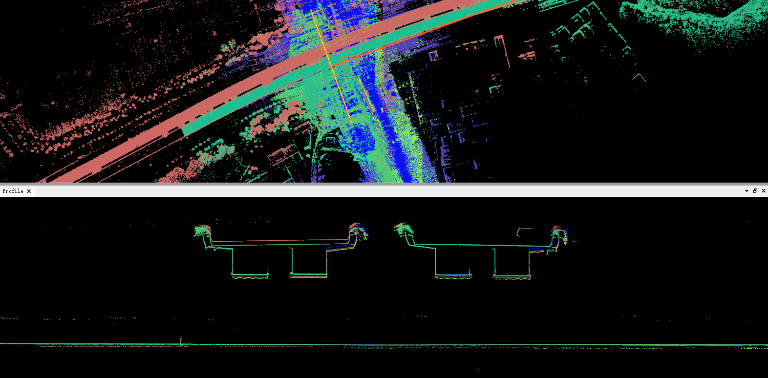
Before multi-engineering air belt splicing
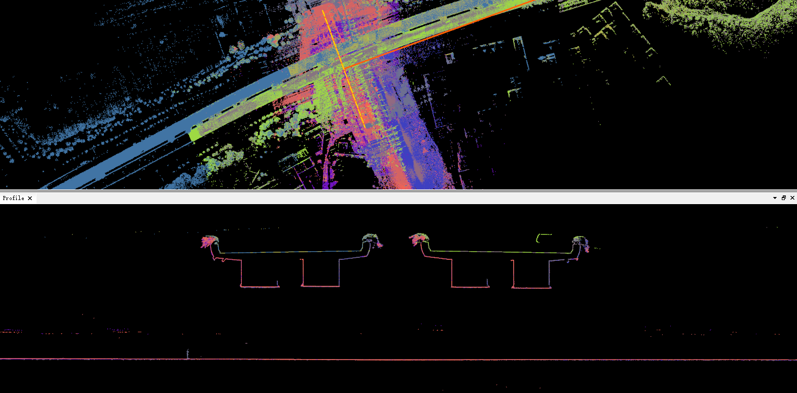
After the multi-engineering air belt splicing