Edit Vertices
Note: After entering node editing mode, the left mouse button will only respond to vector selection, node selection, adding nodes, and similar operations. It will no longer simultaneously respond to rotating the point cloud view. If you need to rotate the point cloud view, you should press and hold the V key on the keyboard while using the left mouse button.
Steps
1.Click the Edit Vertices![]() button in the node editor,Then click to select the vector object of the node to be edited. The dialog box function for vector node editing will be activated. As shown in the figure.
button in the node editor,Then click to select the vector object of the node to be edited. The dialog box function for vector node editing will be activated. As shown in the figure.
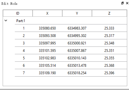
Node editing interface
2.The main functions of the node editor are as follows.
2.1 Selected Highlight : Mouse click on a selected node to edit one or more rows of the table will highlight the selected node of the vector in the 3D scene.
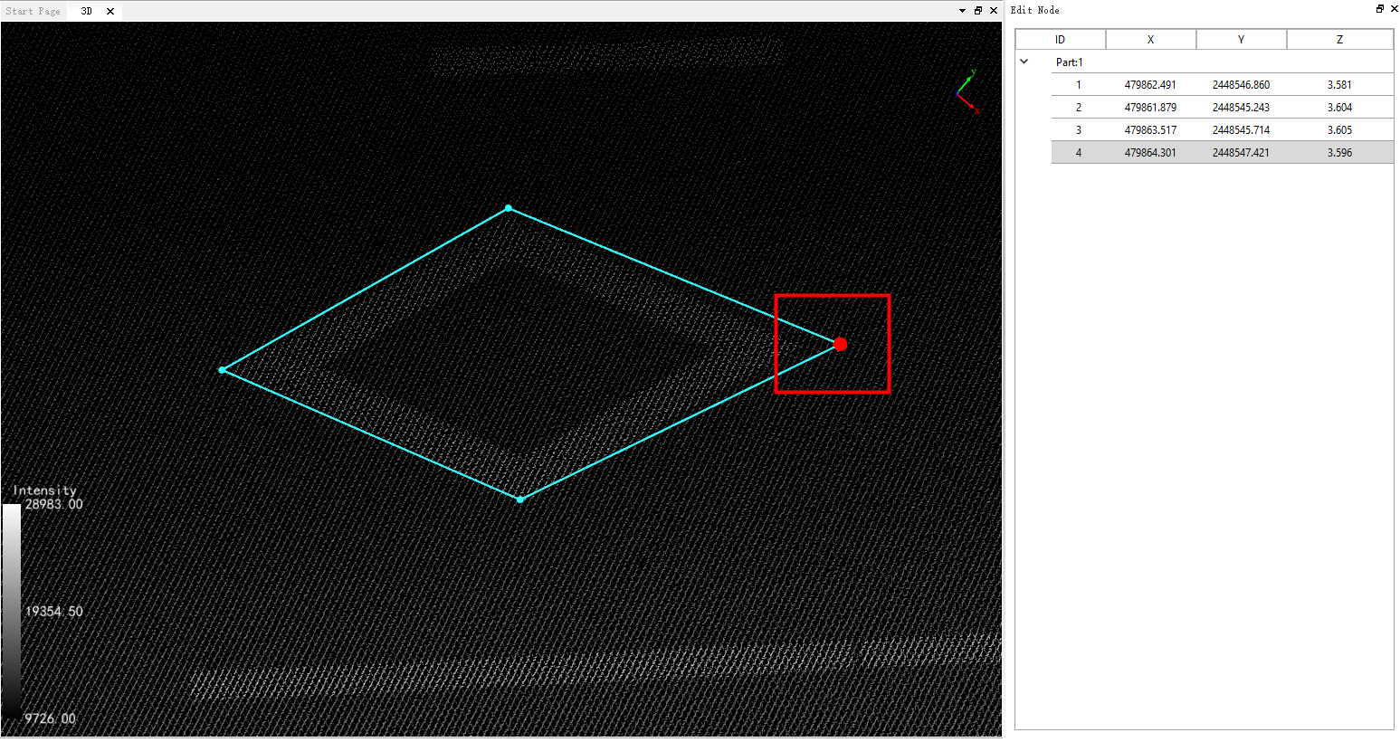
2.2 Center Position: Move the mouse to the line segment, and a red cube will be displayed, indicating the center position of the line segment.
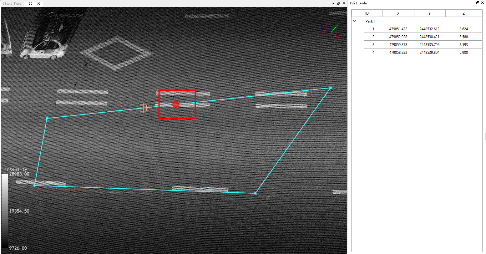
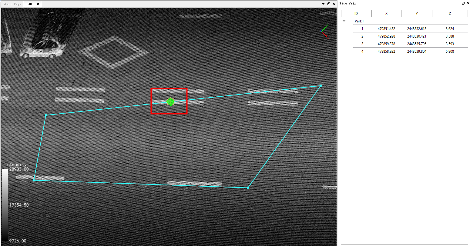
- When the mouse moves to the center position, the red cube turns green, indicating that the center position of the line segment has been captured.
2.3 Double-click to jump, highlight : Double-clicking on a row of the node edit form with the mouse will switch the view of the 3D scene to that node and highlight the node.
2.4 Delete Node: There are two ways to delete a node.
Note: If the node to be deleted is an internal node, the nodes on both sides of the deleted node will be directly connected while the current node is deleted.
- 1.Select a row in the node edit form to delete a node. Or click on the top left cell in the node editing form, select all nodes, and delete all nodes. Take a row as an example, click the right mouse button to bring up the drop-down menu, select the function of "Delete Node", which will delete the corresponding row in the table, and at the same time will delete the selected node of the vector in the 3D scene and redraw the vector. The following figure shows.
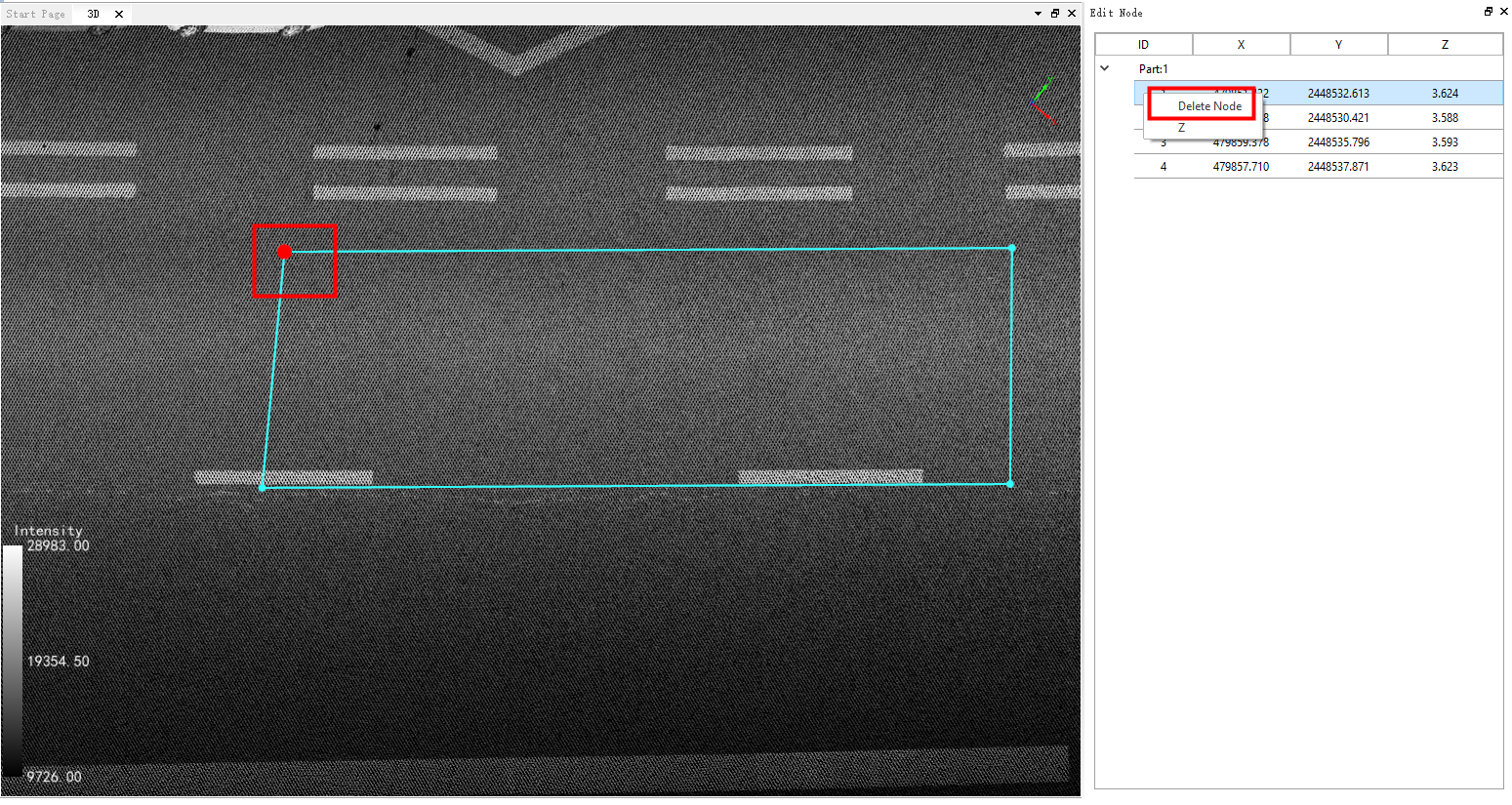
Before node deletion
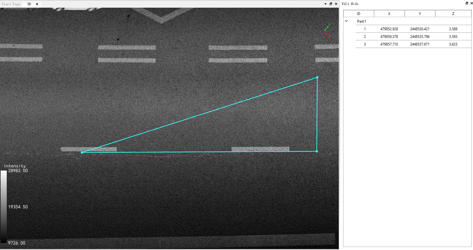
After node deletion
- 2.Move the mouse to the position of the deleted node, the cross wire turns red, indicating that the node is captured. Then click the right mouse button to pop up the drop-down menu, select the function of "Delete Node", which will delete the corresponding row in the table, and will delete the selected node of the vector in the 3D scene, and redraw the vector. The following figure shows.
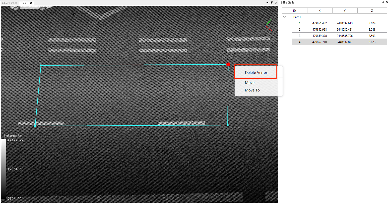
Before node deletion
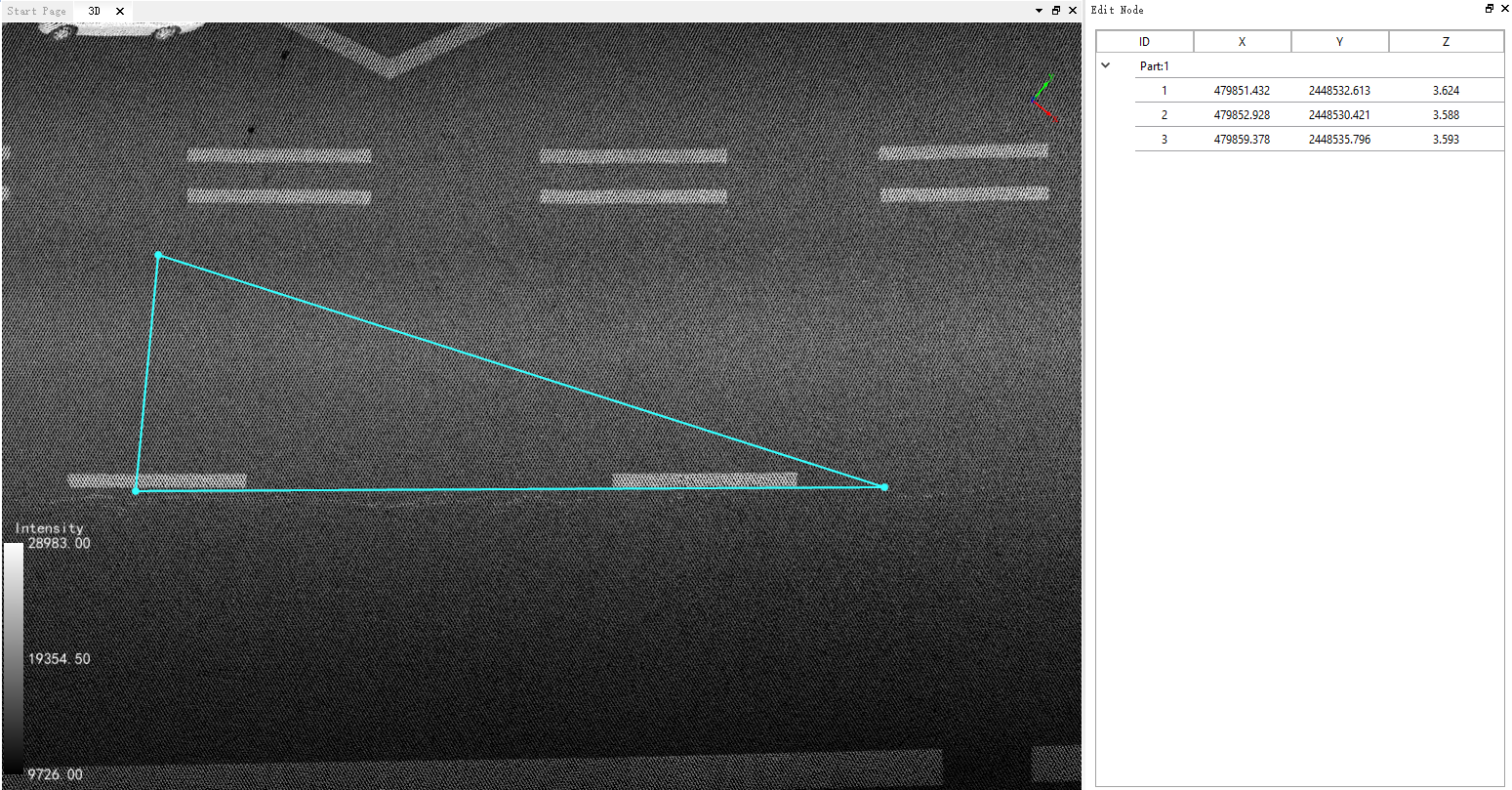
After node deletion
Note: Keep a minimum of one node for the point layer, two nodes for the line layer, and three nodes for the surface layer.
2.5 Add Node: Select the location of the node you want to add in the vector object, the cross turns orange, indicating that the edge of the vector data is captured. Then click the right mouse button, pop-up drop-down menu, select the function of "Add Node", while the vector node will be added in the three-dimensional scene, and the node editing form automatically add the node information. The following figure shows.
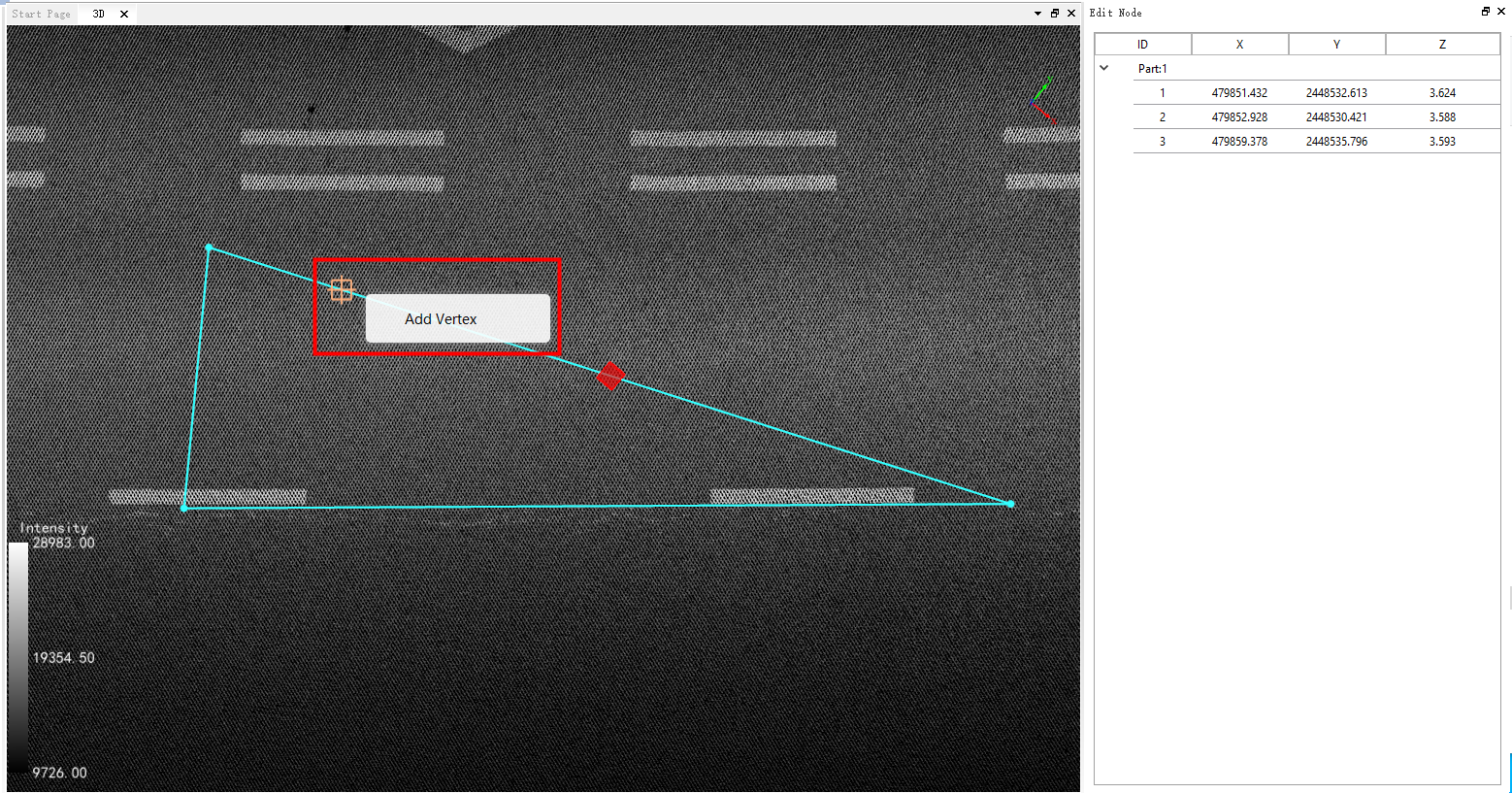
Before node insertion
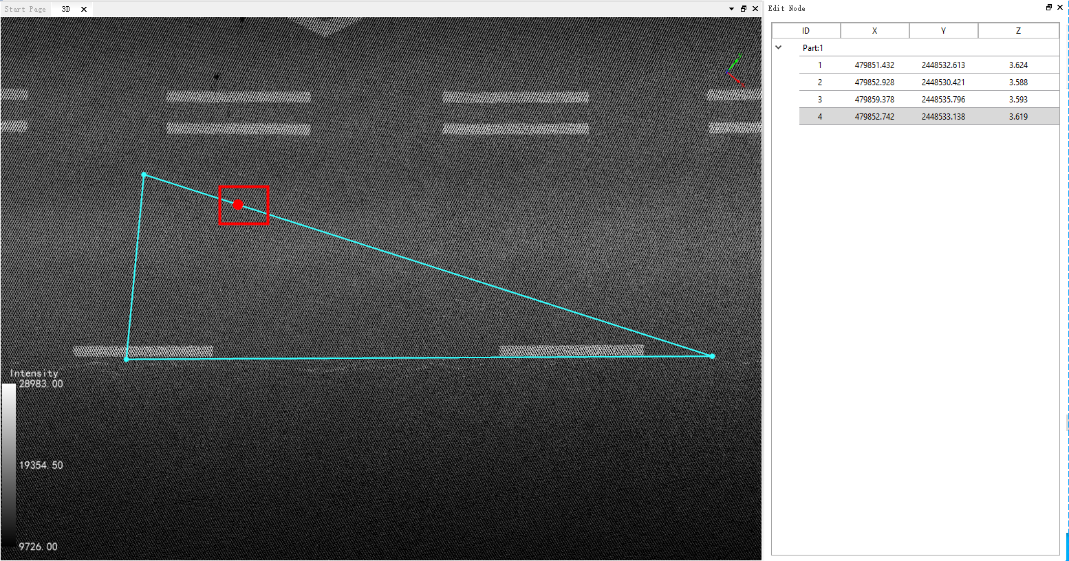
After node insertion
2.6 Move Node: There are two methods.
- 1.When the mouse approaches a vector node, the software automatically snaps to the nearest node, and the crosshair turns red to indicate that it has captured the node. At this point, you can press the left mouse button and drag the node to the desired position. You can also select an edge of the vector to perform a drag and move operation, as shown in the diagram below.
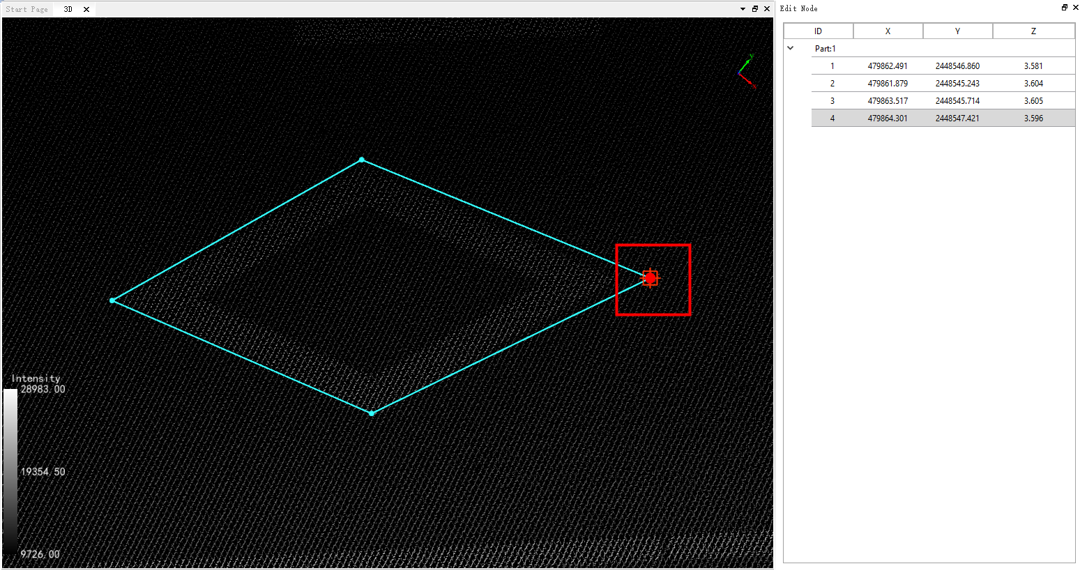
Before moving nodes
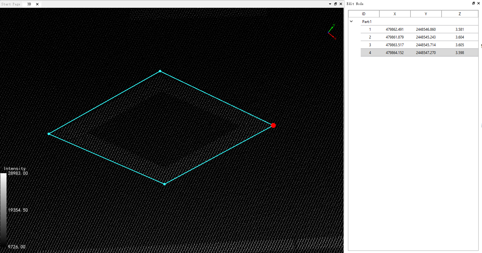
After moving nodes
- 2.When the mouse is close to the vector node, the software automatically captures the nearest node and the cross wire turns red, indicating that the node is captured, then click the right mouse button to bring up the drop-down box.
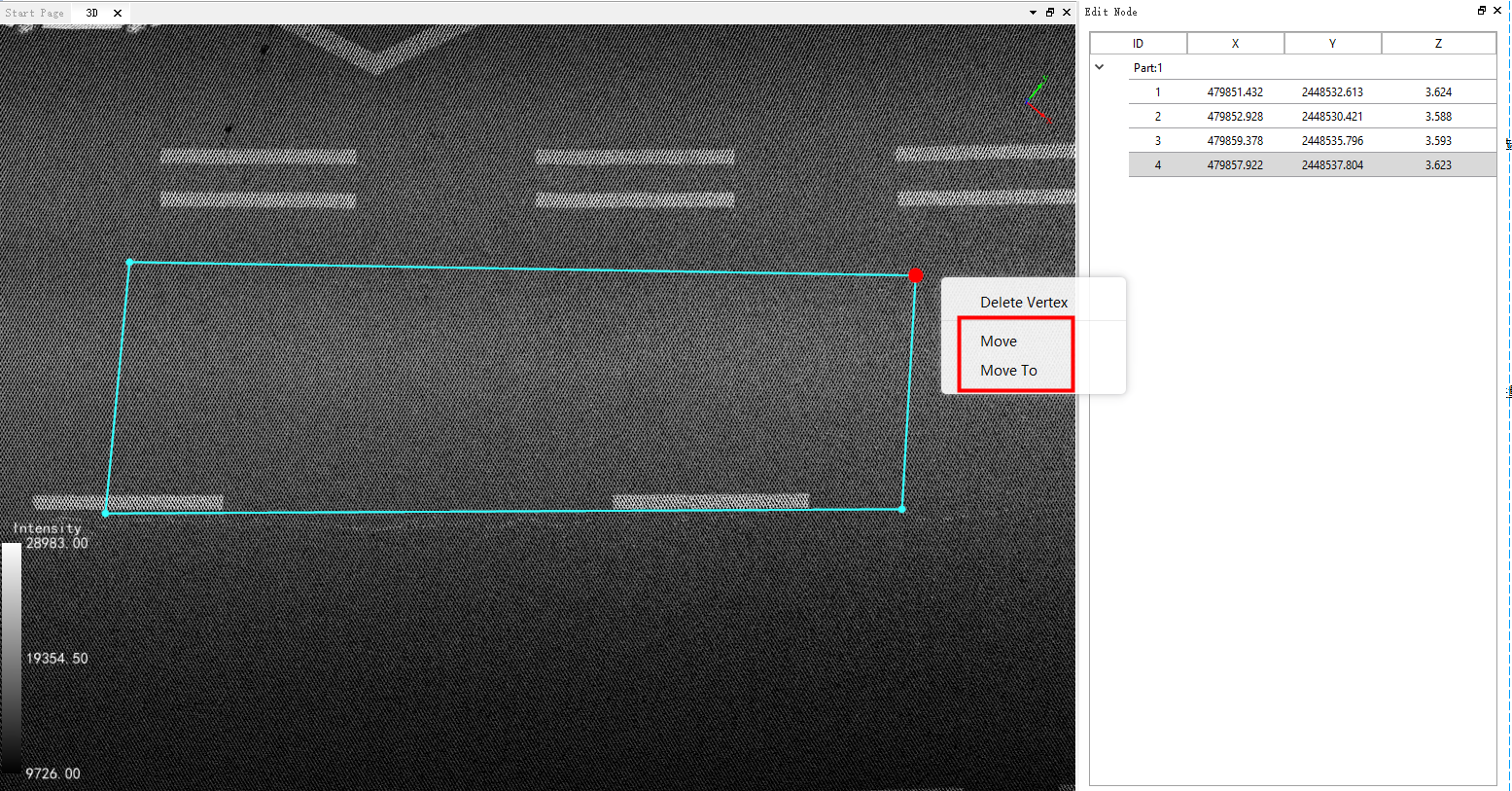
2.1 Check the "Move" function. As shown in the figure below.
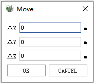
Parameter Setting
- X: The input value is the relative displacement of the node on the X-axis
- Y: The input value is the relative displacement of the node on the Y-axis
- Z: The input value is the relative displacement of the node on the Z-axis
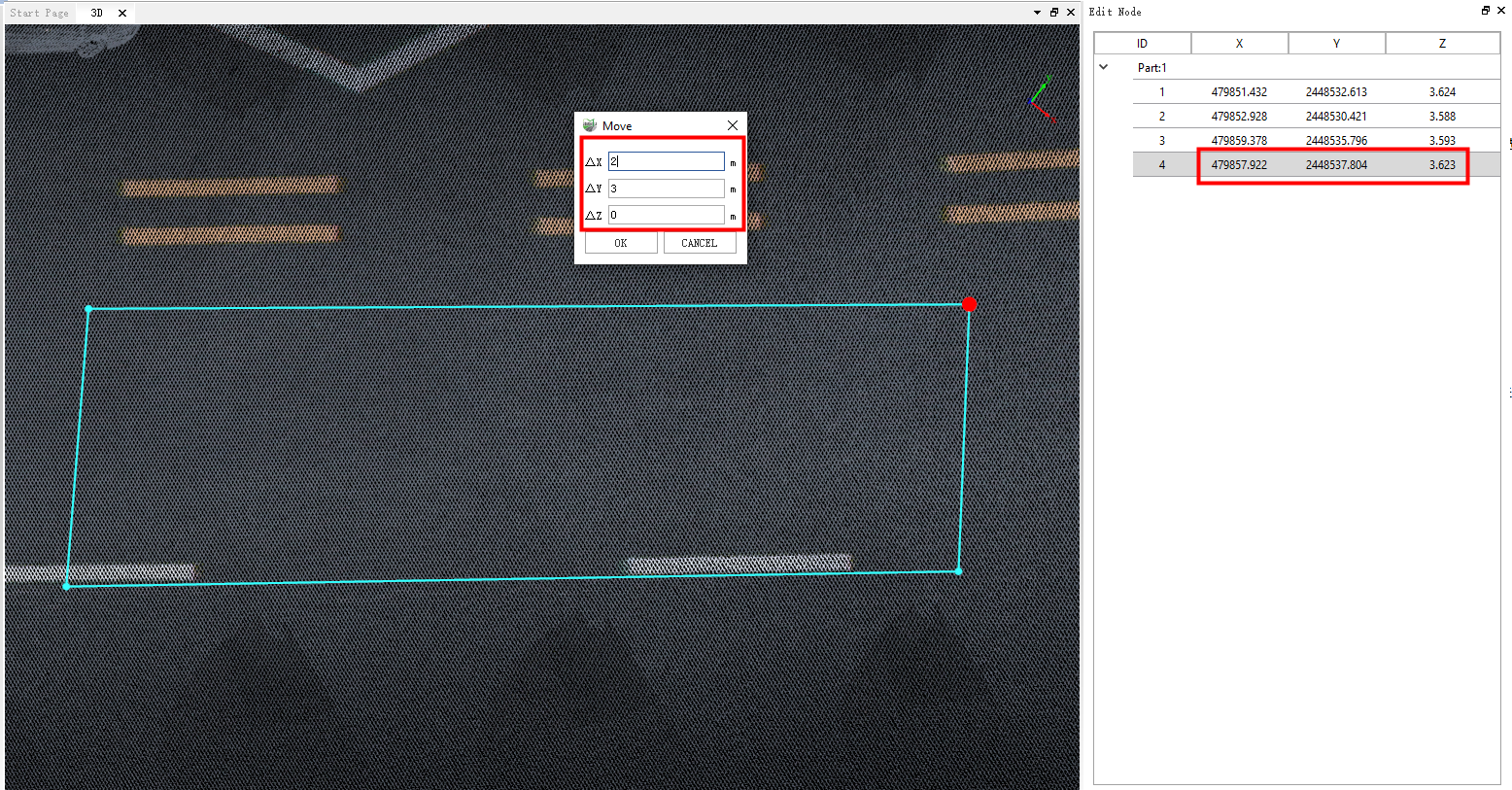
Before moving nodes
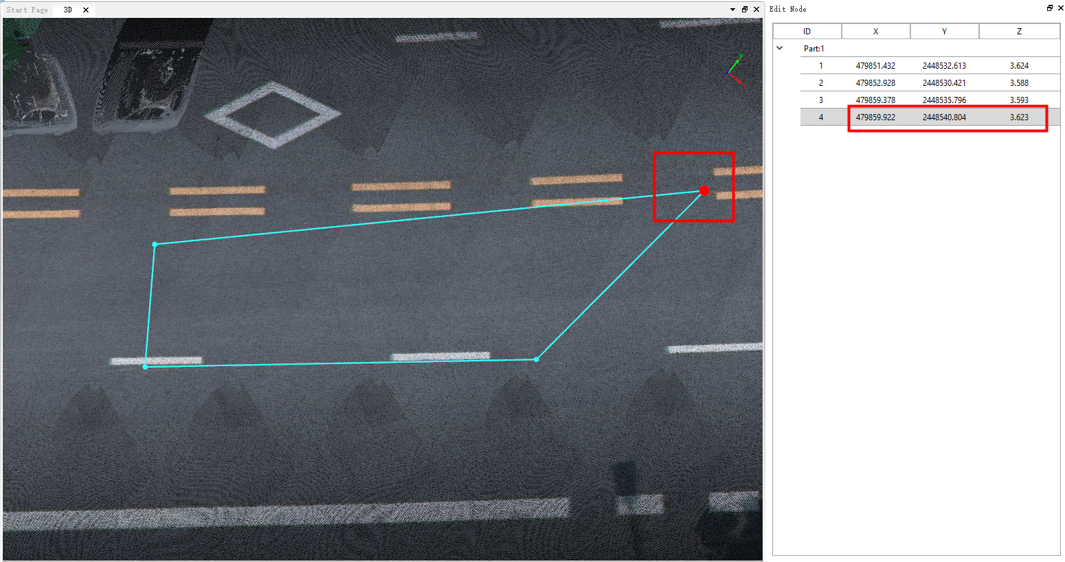
After moving the node
2.2 Check the "Move To" function. The following figure shows.
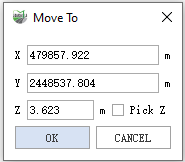
Parameter Setting
- X: The input value is the absolute position of the node on the X-axis
- Y: The input value is the absolute position of the node on the Y-axis
- Z: The input value is the absolute position of the node on the Z-axis
- Pick Z: With the checkbox checked, you can pick any position directly on the point cloud as a Z value
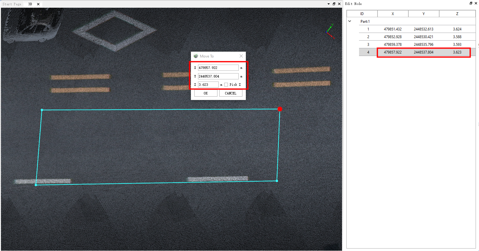
Before moving nodes
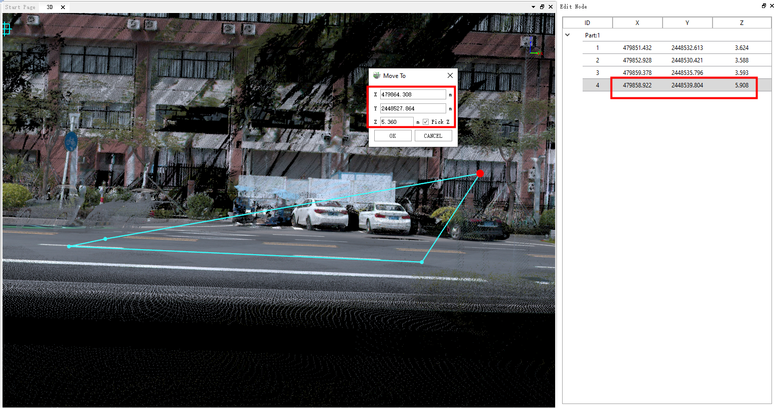
After moving nodes
2.7 Modify Z value: Select a row in the node editing table, then click the right mouse button to bring up the drop-down menu, select "Z" to modify a row. Or click the top left cell in the node editing table, select all nodes, and edit all nodes. Then click the right mouse button to bring up the drop-down menu, select "Z" to modify all nodes.
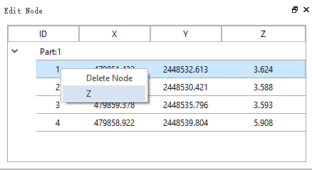
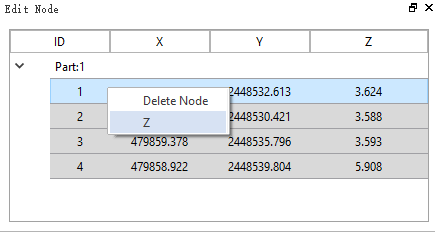
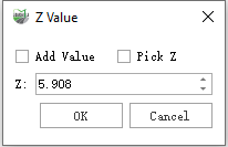
The dialog box of Modify Z Value will pop up:
- Add Value:Unchecked "Add Value" will modify the Z value of the selected node to the value in the input box and redraw the vector. If "Add Value" is checked, a new value will be added to the original Z value of the node, and the vector will be redrawn in the 3D scene.
- Pick Z:When add Value is unchecked, the checkbox for Select Z can be checked directly, and any position on the point cloud can then be picked as a Z value
3.Shortcut:
| Function | Shortcut | Description |
|---|---|---|
| Z Value | Q/q | While adjusting vector nodes, you can use the Q key to bring up the elevation adjustment window and adjust the elevation value of the nodes. |
| Insert the Vertex | I/i | While editing vector nodes, you can use the I key to add a node at the desired location. |
| Delete the Vertices | Delete | While editing vector nodes, you can use the Delete key to delete unwanted nodes. |
| Lasso Pick Vertices | Shift + drag the left mouse button | While editing vector nodes, you can use Shift + drag the left mouse button to lasso-select the nodes you want to edit. |
| Rotate Point Clound | V/v + drag the left mouse button | While editing vector nodes, you can use V/v + drag the left mouse button to move the point cloud. |
Vector editing with topological edge structure.
In node editing, if you check "With Topology," you can modify overlapping vector edges and nodes. When you move, add, or delete shared nodes, it will simultaneously apply to the nodes or edges shared by line features or polygon features.
1.Click the Node Editing![]() Button,check the "With Topology" checkbox, and then use the mouse to click on the vector object you want to edit. You will see that if the vector has topological edges, when the mouse captures an edge, that edge will be highlighted in red, indicating that topological edge editing can be performed, as shown in the image.
Button,check the "With Topology" checkbox, and then use the mouse to click on the vector object you want to edit. You will see that if the vector has topological edges, when the mouse captures an edge, that edge will be highlighted in red, indicating that topological edge editing can be performed, as shown in the image.
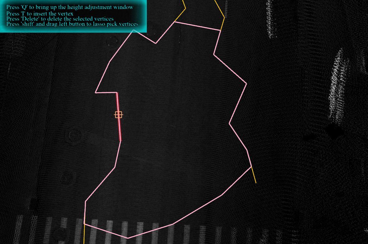
At this point, when you click on the topological edge you want to edit, a page will pop up on the right side, listing the multiple layers where the current edge is located.
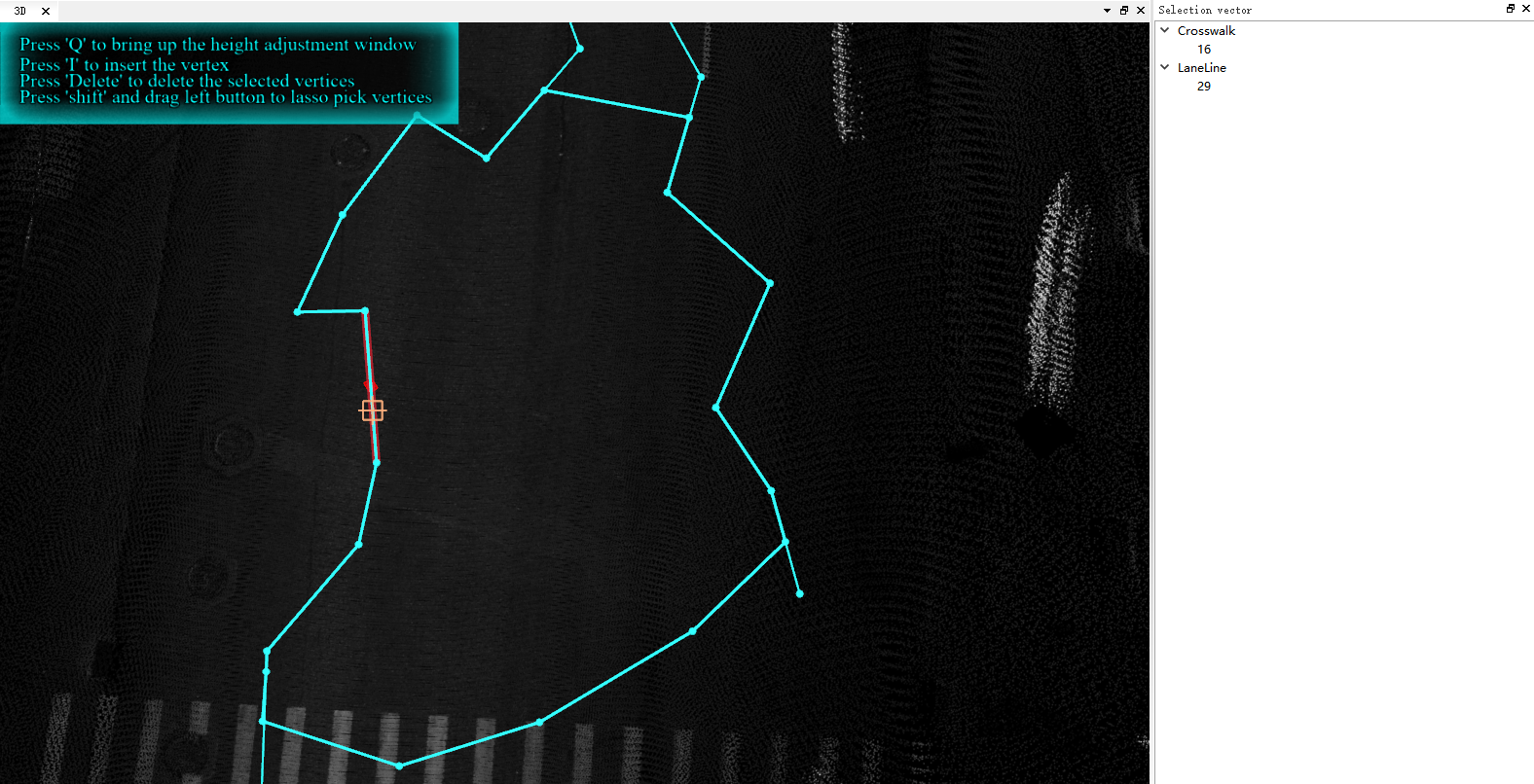
2.The main functions of topological edge and node editing, which affect multiple layers where the currently selected edge resides, are as follows:
(1)Edge Movement: You can directly drag the currently selected edge to the desired position with the mouse to achieve movement.
(2)Delete Node: Deleting nodes is the same as normal node editing. You can select a node and then right-click to delete it, or you can use the Delete key.
(3)Add Node: Adding nodes is similar to normal node editing. You can right-click to add a node or use the shortcut key "I" to add one. When a red box appears, indicating the center of the current edge, you can capture it and click to add a node.
(4)Move Node: Moving nodes is the same as normal node editing. You can directly drag the node to move it, or when you capture a node, you can right-click and use "Move" or "Move To" to perform the movement.
Compared to regular node editing, node editing on shared edges cannot be performed in the node editing list, and you cannot use the shortcut key "Q" to bring up the modification dialog. All other operations are the same.