Boresight Calibration
Steps
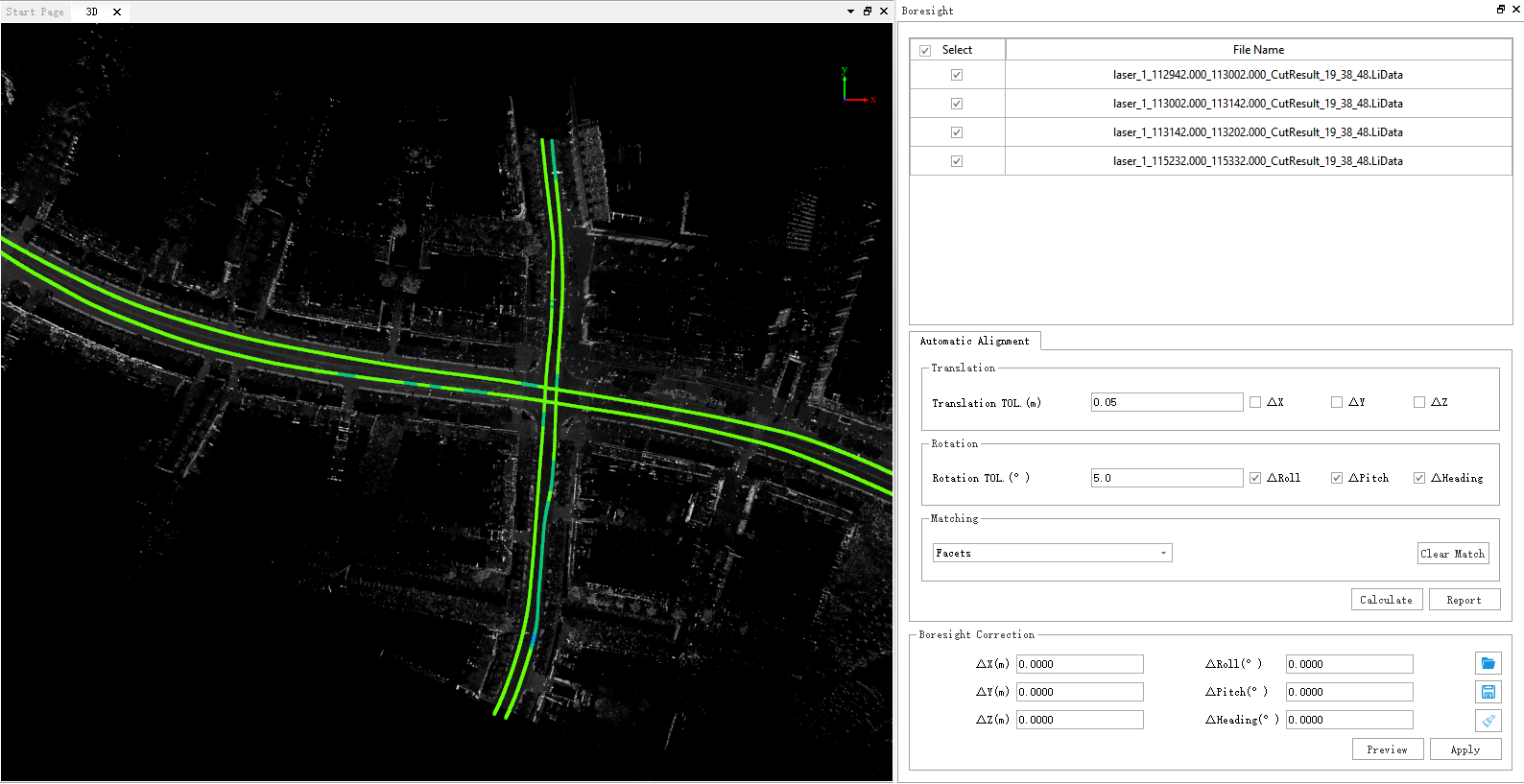
1.Click Boresight ![]() button, the placement interface will pop up on the right side of the user interface. This function is mainly used to correct the placement error of the laser, and the point cloud data will be transformed according to the corrected value. To obtain high-quality point cloud data, the selection of laser placement error correction values is particularly important. This software provides two methods: automatic placement error correction and manual placement error correction.
button, the placement interface will pop up on the right side of the user interface. This function is mainly used to correct the placement error of the laser, and the point cloud data will be transformed according to the corrected value. To obtain high-quality point cloud data, the selection of laser placement error correction values is particularly important. This software provides two methods: automatic placement error correction and manual placement error correction.
2.Automatic placement error correction:
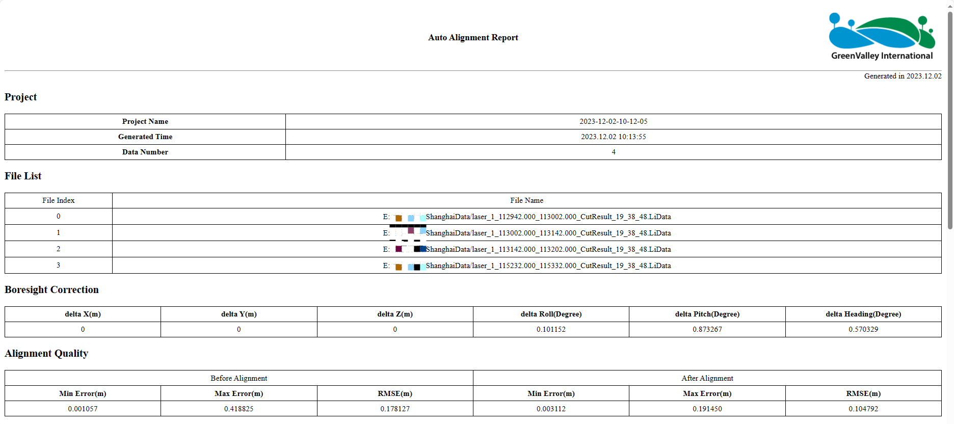
Check the final placement error that needs to be calculated in the placement interface, enter the translation tolerance and rotation tolerance, and Boresight After clicking calculate, the software will automatically calculate the placement error and display the results in the placement error correction parameter box. After the placement error is calculated in the automatic placement error correction mode, the software will count the alignment quality and generate an HTML report. Click on the report to open the generated HTML report. For the relevant principles of automatic placement error correction, please check Automatic Calculation of Placement Error.
3.Manual Calculation of Placement Error:
Users can also enter the placement error correction parameters by themselves. For manual calculation of placement error, please refer to Manual Calculation of Placement Error. Click the "Preview" button, the error correction value will temporarily act on the selected point cloud, but the point cloud file on the disk has not been modified. If the preview effect is better, you can click the “Apply” button to fix the error to the point cloud file that is actually applied to the disk. Whether it is an automatic method or a manual method, in the process of correction, you can use the profile tool to view the correction results, as shown in the figure.
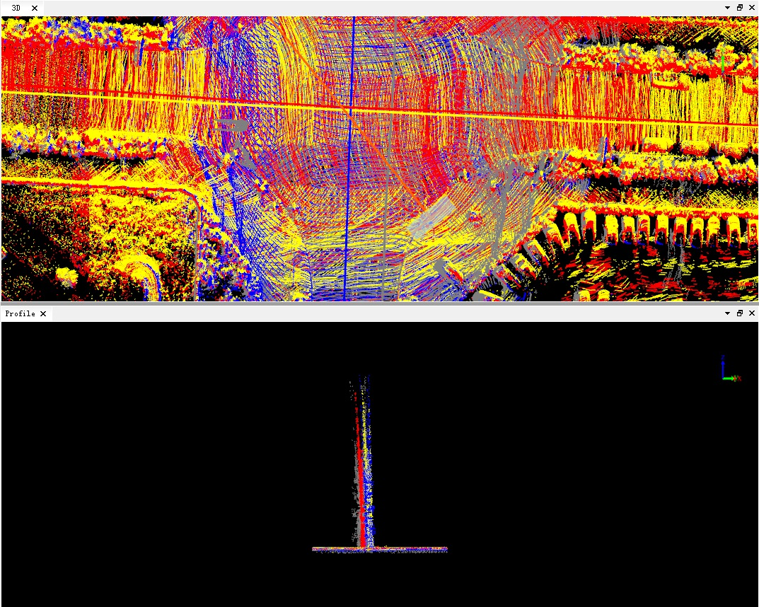
Before correction
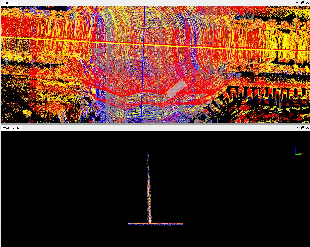
After correction
4.Click the Report button to view the placement error correction quality report, as shown in the figure.
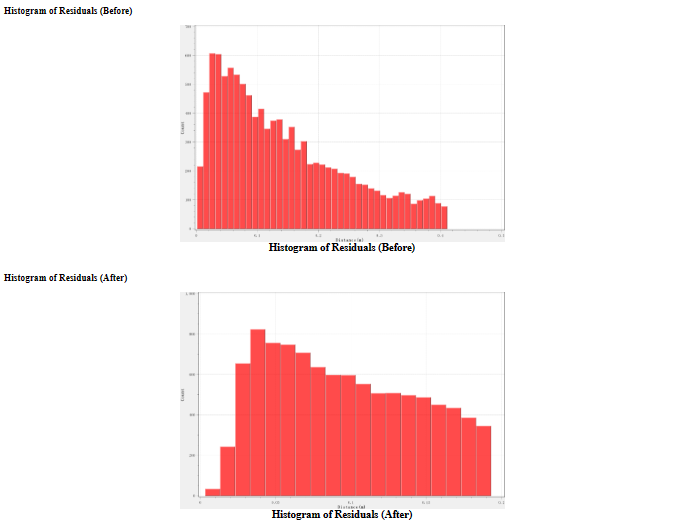
5.Click the Clear Match button to delete the matching information, and calculate it again after changing the relevant parameters.
6.You can load the error correction file in turn through the three buttons on the right, save the current parameters as an error correction file, or clear the currently set correction value.
Parameter setting
- Placement Error Correction
- ΔX/ΔY/ΔZ: Set the offset error correction parameter.
- ΔRoll/ΔPitch/ΔHeading: Set the attitude error correction parameters (roll, pitch, yaw).
- Automatic Alignment: The program automatically matches the relevant points of the segmented point cloud, and calculates the optimal placement error correction value through the adjustment.
- Translation Tolerance: The maximum translation adjustment range corresponds to ΔX, ΔY, and ΔZ, and the default setting of the program is 0.05 meters.
- Rotation Tolerance: The maximum rotation adjustment range corresponds to ΔRoll, ΔPitch, and ΔHeading. The default setting of the program is 5°.
- Optional Items: The user can freely choose whether 3 translation quantities and 3 rotation quantities participate in the adjustment and calculate the correction value. It is not recommended to correct ΔZ when processing aviation down-view data. All rotation quantities are checked by default, while all translation quantities are not checked. Better results can be obtained by using the default values.
- Matching: Users can choose two matching methods: facet piece matching and sampling point matching.
- Facets: Uniformly extract high-order facets combinations in the overlapping area of the data to be matched (relatively robust on data with this feature).
- Sampled Points: The sampling point is extracted by analyzing the significance of the data to be matched, and then matched based on the sampling point and its normal vector.