Clearance Analysis
Steps
1.Click the Clearance Analysis  button to open the Clearance Analysis dialog box.
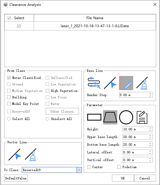
2.Select data for the analysis in the Input Data (select at least one) area. Point clouds and line features can be selected separately or together.
3.Select how to obtain the path in the Analysis Path area and set the Trajectory Sampling Interval as needed.
4.Select a rectangle, trapezoid, circle, or custom template in the Section Template area, and set the template dimensions and offset parameters.
5.To adjust how the clearance area is displayed, click Display Settings and configure the required options.
6.Click OK to start the analysis. After the analysis is complete, view the results in the Clearance Data Manager and export a clearance analysis report as needed.
Input Data
Point Cloud
Select: Select the point cloud files to include in the analysis.
From Class: Specify the point cloud class to include in the clearance analysis.
To Class: Specify the class assigned to point clouds that enter the clearance area after analysis.
Line Feature
Pick Vector Line: Select one or more existing line features in the 3D window for the analysis.
Clear Vector Line: Clear the currently selected line features.
Analysis Path
The analysis path determines the direction and range for placing section templates. Specify it using one of the following methods:
- Select on Trajectory: On a loaded trajectory, click the start point, move the mouse along the trajectory, and click the end point to select a trajectory segment. Multiple trajectory segments can be selected continuously.
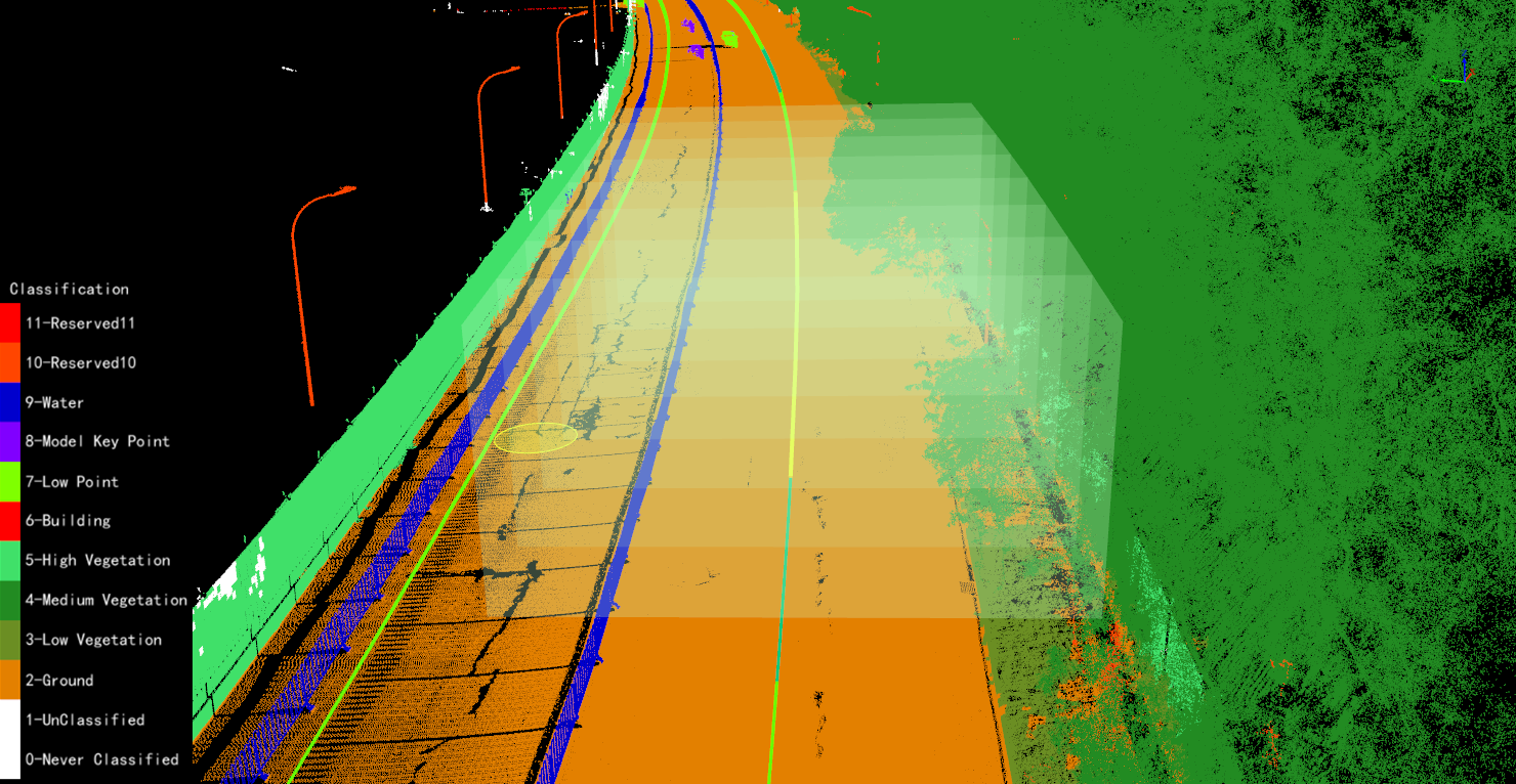
- Pick Base Line: Select one or more existing vector lines in the 3D window as the analysis path.
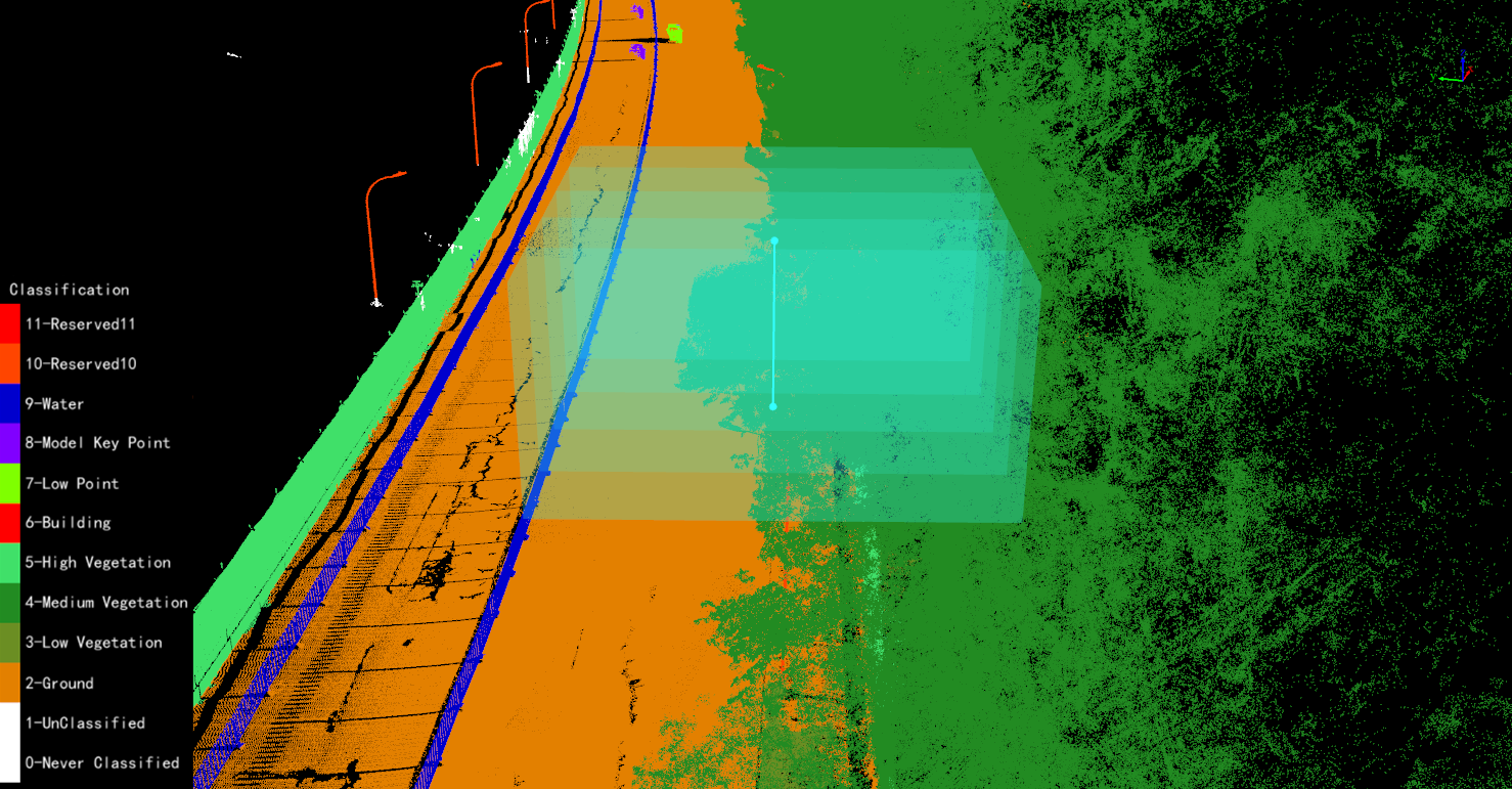
- Draw Base Line: Draw a temporary vector line at the location to be analyzed as the analysis path.
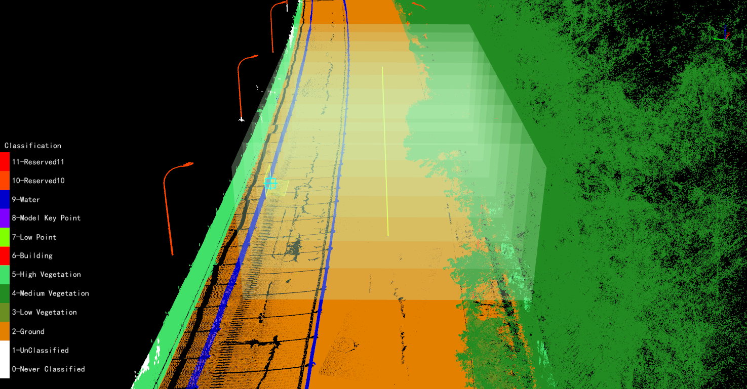
Clear Base Line: Clear the currently selected or drawn analysis path.
Trajectory Sampling Interval: The interval for generating section templates along the analysis path. The unit automatically follows the point cloud coordinate system. This parameter controls the analysis sampling density along the trajectory. A smaller value generates more densely spaced analysis sections.
Section Template
The section template defines the shape and dimensions of the clearance area. The dialog box provides rectangle, trapezoid, circle, and custom templates.
Rectangle
- When Center on Path is not selected, the midpoint of the bottom edge of the rectangle is located on the analysis path.
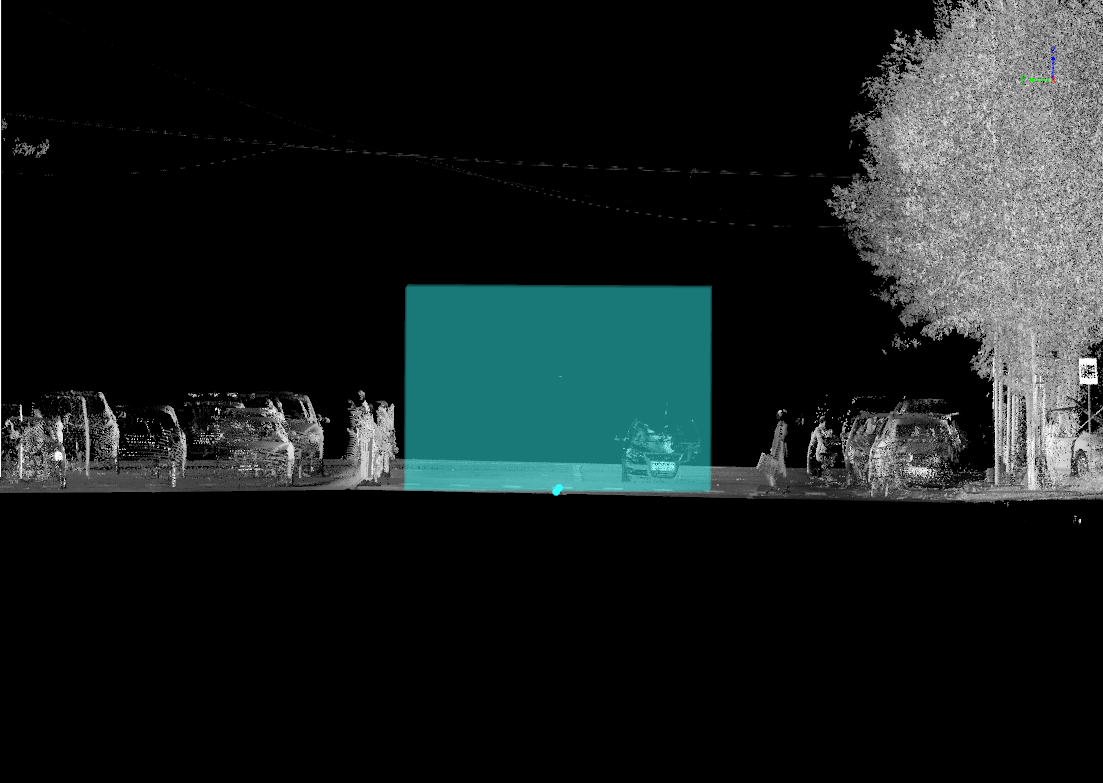
- When Center on Path is selected, the geometric center of the rectangle is located on the analysis path.
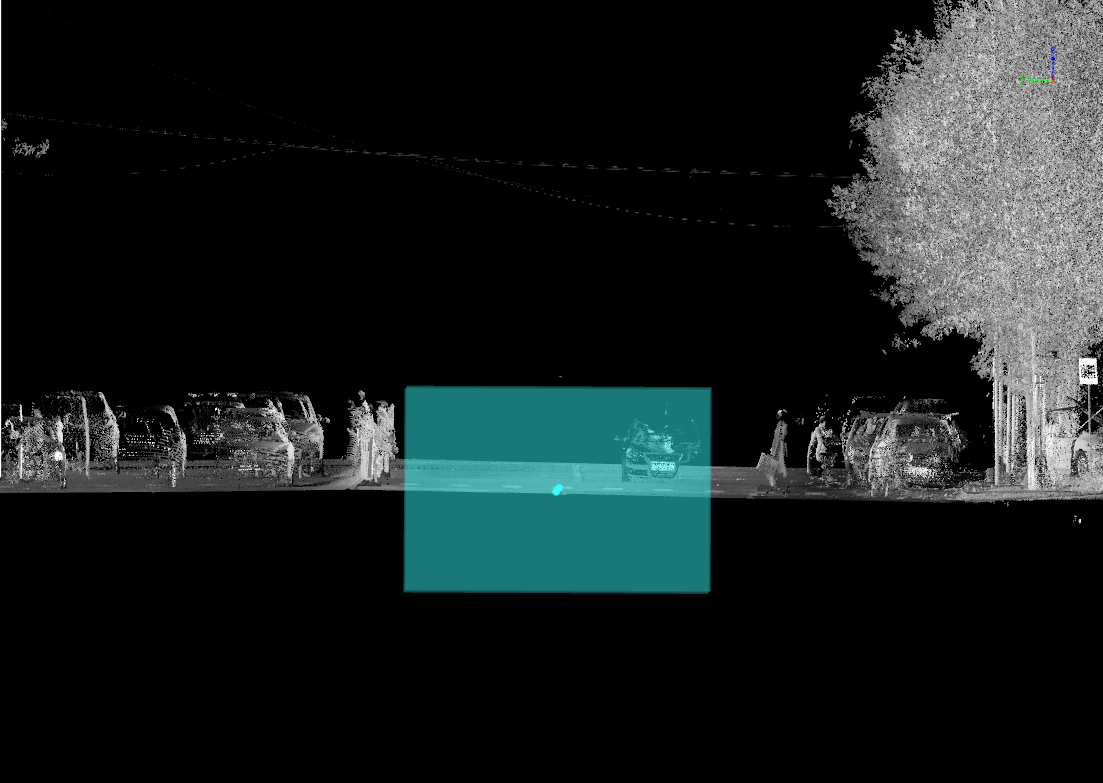
Height: Set the height of the rectangular clearance area.
Width: Set the width of the rectangular clearance area.
Trapezoid
- When Center on Path is not selected, the midpoint of the bottom base of the trapezoid is located on the analysis path.
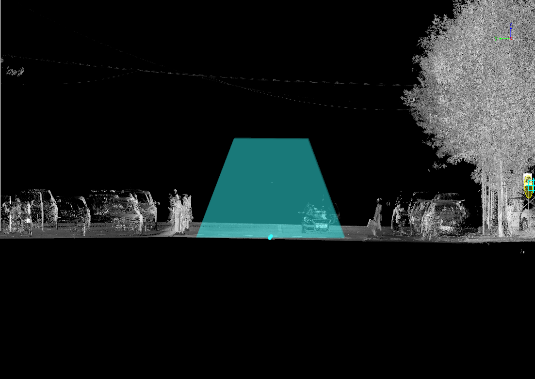
- When Center on Path is selected, the geometric center of the trapezoid is located on the analysis path.
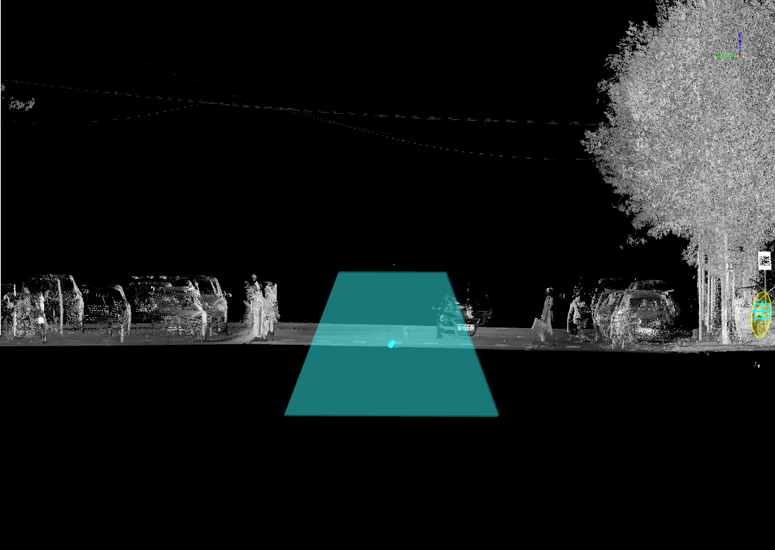
Height: Set the height of the trapezoidal clearance area.
Upper Base Length: Set the length of the upper base of the trapezoid.
Bottom Base Length: Set the length of the bottom base of the trapezoid.
Circle
- When Center on Path is not selected, the lowest point of the circle is located on the analysis path.
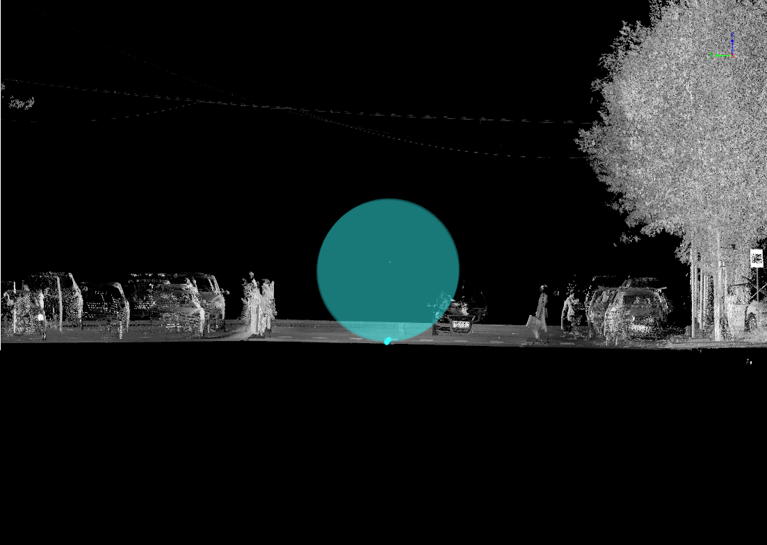
- When Center on Path is selected, the center of the circle is located on the analysis path.
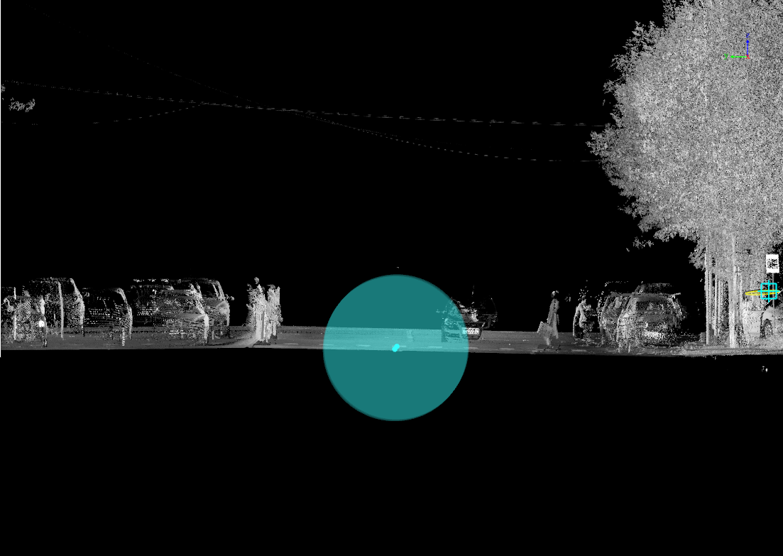
- Radius: Set the radius of the circular clearance area.
Custom
After selecting the Custom template, select a point on any vector line. The profile window displays the point cloud profile along the tangent direction, where you can draw a polygon template.
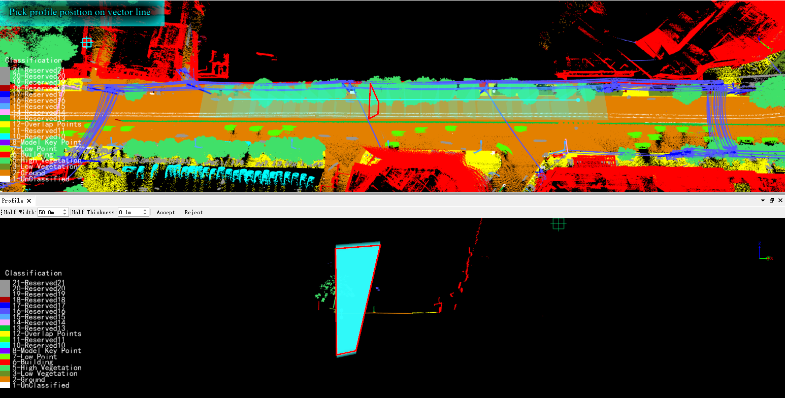
Half Width: Set the half width of the point cloud profile display.
Half Thickness: Set the half thickness of the point cloud profile display.
Length: The upper-left corner of the window displays the distance between the current mouse point and the previous point in real time.
Accept: Use the currently drawn polygon as the section template.
Reject: Discard the current drawing.
Common Parameters
Lateral Offset: The lateral distance between the section template and the analysis path. In the forward direction of the analysis path, the left side is negative and the right side is positive.
Vertical Offset: The vertical distance between the section template and the analysis path. Above the path, in the positive Z-axis direction, is positive; below the path is negative.
Center on Path: Specify whether the geometric center of the template is located on the analysis path. This option applies to rectangle, trapezoid, and circle templates.
Display Settings
Click Display Settings to adjust the appearance of the clearance area. Display settings affect only visualization in the 3D window and do not change the clearance analysis results.
Preview Interval: Set the interval at which the clearance area preview is displayed along the analysis path. The unit automatically follows the point cloud coordinate system.
Color: Set the display color of the clearance area preview.
Transparency: Set the transparency of the clearance area preview.
Solid Preview: Select this option to display the clearance area preview as a continuous solid. When it is cleared, sections are displayed at the specified preview interval.
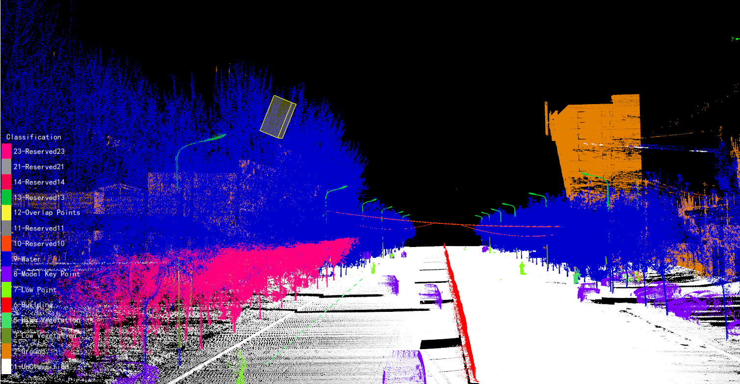
Analysis result
Other Buttons
Default Value: Restore the dialog box parameters to their default values.
OK: Run the clearance analysis with the current settings.
Cancel: Close the dialog box without running the analysis.