Adjust Elevation Report
Feature Description: The elevation adjustment report tool will create an elevation difference report between the laser point cloud and the ground control points, which can be used to check the elevation accuracy of the laser point cloud and improve its height using calculated correction values
Process accuracy.
A control point file is a comma separated text file, with each row consisting of three columns: X, Y, and Z, with the first row being the header. At least three are needed Control points are required to successfully create control point reports.
The output report displays information on the elevation difference between the laser point cloud used and the elevation control points. Statistical information on the elevation difference includes the average amplitude, standard deviation, mean square error, average elevation difference, and maximum and minimum elevation difference values.
Step
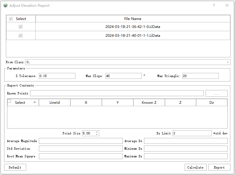
1.Click Adjust Elevation Report ![]() button,Pop up dialog box interface.
button,Pop up dialog box interface.

Parameter Settings:
- Input Data: Choose the LiData file(s) you need to export. The input file can be a single-point cloud data file or multiple data files.
- From Class: The default is all available categories, and users need to select the point cloud category that uses control points to check elevation accuracy. Generally, hard surface point clouds such as ground points, building points, etc. are selected.
- Z Tolerance: The height difference between the three nearest points. Due to the fact that the triangles constructed from the nearest points may be very small, the small distance may result in calculated slope values being smaller Exceeding the set maximum slope value. In this case, if the height difference value of the nearest point is within the tolerance range, the current calculation result is considered valid. In general, this value can be determined based on the thickness of the point cloud Adjust the situation.
- Maximum Slope: Maximum terrain slope tolerance. If the slope is greater than this value, the elevation difference will not be calculated. Generally, control points will be selected on relatively flat terrain, so if the slope Too large, easily influenced by incorrect information.
- Maximum Triangle: The length of the maximum triangle is used to avoid large deviations caused by elevation interpolation. If the side length of the triangle is too large, it indicates that the control point corresponds to the point cloud area The initial category points of the domain are too few, resulting in a large error in the calculated elevation difference.
- Known Points: Input control point file.
- Point Size: The data in the control point report list can be double-click to locate and display the corresponding control point in the window. The point size is set to display the size of the control point in the window.
- Dz Limit: Set the tolerance of Dz. To detect height differences with significant errors between the laser point cloud and control points. Maximum tolerance = Mean height difference + Dz tolerance × standard deviation;Minimum tolerance = Mean height difference - Dz tolerance × standard deviation.
- Calculation: After the user sets the parameters, click this button to calculate the height difference.
- Export: Export a control point report file in txt format, which contains elevation error information of point cloud data and statistical information of Dz.
- Transformation Model Definition: Five computation methods are provided for geoid model solving: planar fitting, polynomial curve fitting, quadratic surface fitting, cubic surface fitting, and linear transformation. Based on these methods, the XYZ validation mode additionally supports three transformation relationship computations: four-parameter transformation, seven-parameter transformation, and 3D affine transformation. Among them, the linear transformation computes ΔX, ΔY, and ΔZ based on the positions obtained from target recognition and the corresponding control point coordinates. For details, see Create Transformation Relationship.**