Settings
Step
1.Active Project
In the directory tree of the project window, right-click the *.liscan project name that requires parameter configuration, and click the Set Aactive Project button in the pop-up drop-down list. The name of the project will be highlighted.
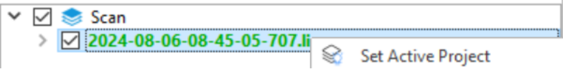
Set Aactive Project
2.POS Process Parameter Settings
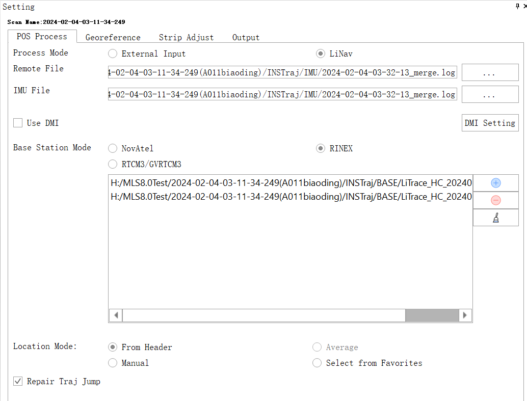
After opening the *.liscan project, the Settings dialog box will automatically pop up on the right side of the software, and the POS Process interface will be displayed by default.
Settings_POS Process
Parameter Description
- Proces Mode_Linav: Post-process POS file by LiNav module. Click LiNav and turn to LiNav page, set base station and rover station data. The result POS file is in *.pos format.
- Rover Station File: GNSS data obtained by field collection equipment.
- IMU File: INS data acquired by field acquisition equipment.
- DMI: If the user has collected DMI data, check DMI, and then click the DMI Setting button to pop up the DMI Option dialog box. The user needs to measure the lever arm position and wheel circumference by themselves. And fill in the measurement data accurately. For specific measurement methods, see DMI Installation Instructions.
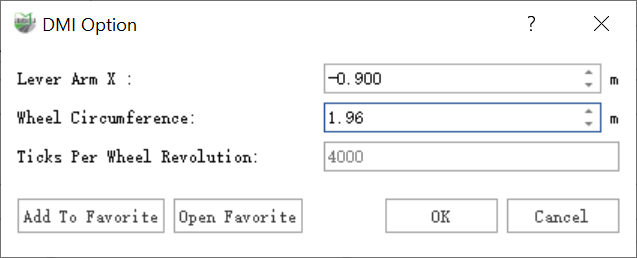
DMI Option
- Base Station Data:The base station data has four modes: NovAtel, RINEX, and RTCM3/GVRTCM3.
- Location Mode: Calculation mode of base station coordinates.
- From Header: Read from header. The default selection when the base station is Rinex.
- Manual: Manual input mode, input WGS84 longitude and latitude coordinates (optional degree minute second format or degree format), ball height and antenna. When setting the latitude and longitude, when the actual latitude is positive, north should be selected, otherwise south should be selected. If the actual longitude is positive, choose east, otherwise choose west. Fill in the longitude and latitude values as positive numbers. After manually adding the base station coordinates, click the Save to Favorites button. In the pop-up Favorites dialog box, the user needs to enter the name. After clicking the Confirm button, the parameters will be Record in favorites.At the same time, the software also supports custom selection of coordinate system, and the conversion can be performed by entering X, Y, Z and antenna height.
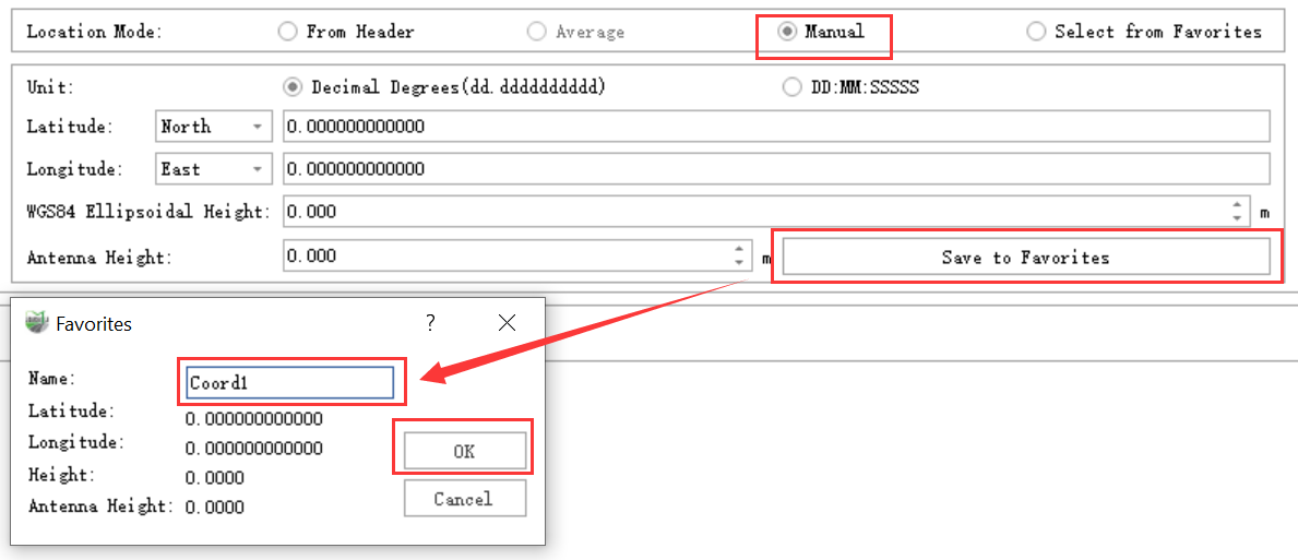
Location Mode_Manual
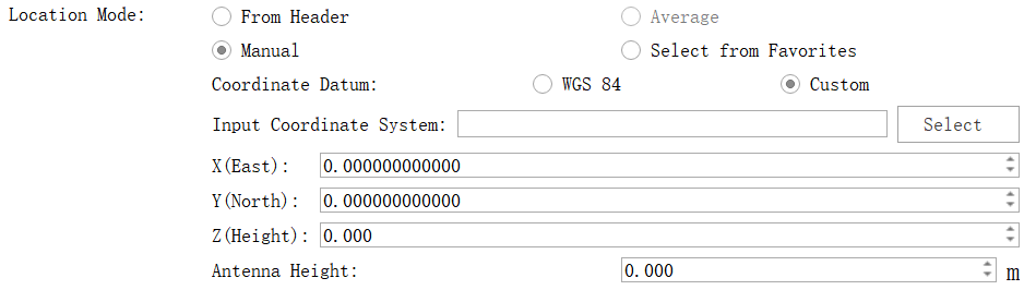
Location Mode_Manual
- Select from Favorites: Select base station coordinate parameters from the favorites list. Click the Select from Favorites button, and you can view the coordinate list in the pop-up Favorites dialog box. Select the required coordinates and click the OK button. If you need to delete the entry, select it and click Just click the Delete button. When used for the first time, the list is empty and needs to be entered in manual mode and click Save to Favorites to save.
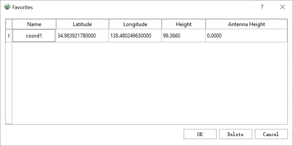
Favorite
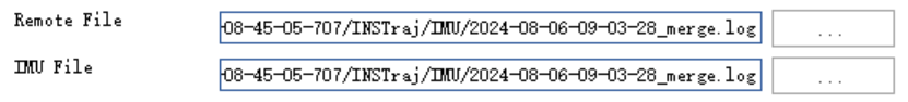
The software will automatically read the GNSS and inertial navigation data collected by the LiMobile M1 mobile laser scanning system.
GNSS and inertial navigation data collected by LiMobile M1(*merge.log)
- Proces Mode_External Input: Import existing trajectory files. Click the External Input button to switch the page to external input mode. Click to select the corresponding file, and the Open ASCII File dialog box will pop up.
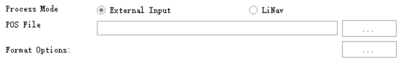
Proces Mode_External Input
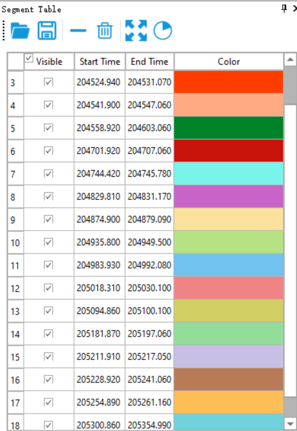
- Repair Traj Jump: Used to detect and repair trajectory segments with horizontal/elevation jumps in the trajectory. If it is not checked, the software will detect the jump segments in the POS Process step; if it is checked, after the software detects the jump segments, it will repair the segment accordingly.
Users can click Segment Table on the trajectory menu bar to view jump segments.
Segment Table
3.Georeference Parameter Settings
The user needs to switch the Settings dialog box to the Georeference tab bar.
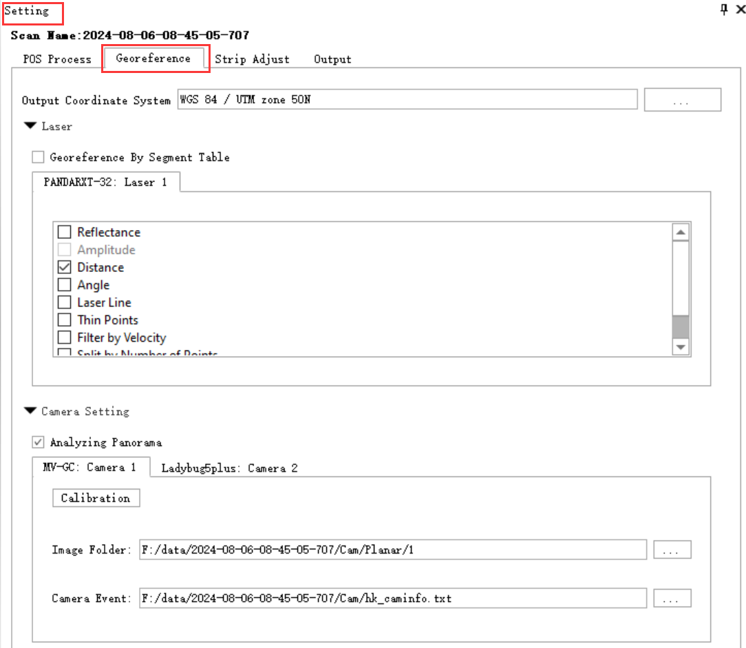
Settings_Georefence
Parameter Description
- Output Coordinate System: Automatically identify the target coordinate system for the POS file imported or generated in the previous step. By default, the coordinate system of the WGS84 UTM 6-degree zone where the current collection is located is recommended. To edit click the button.
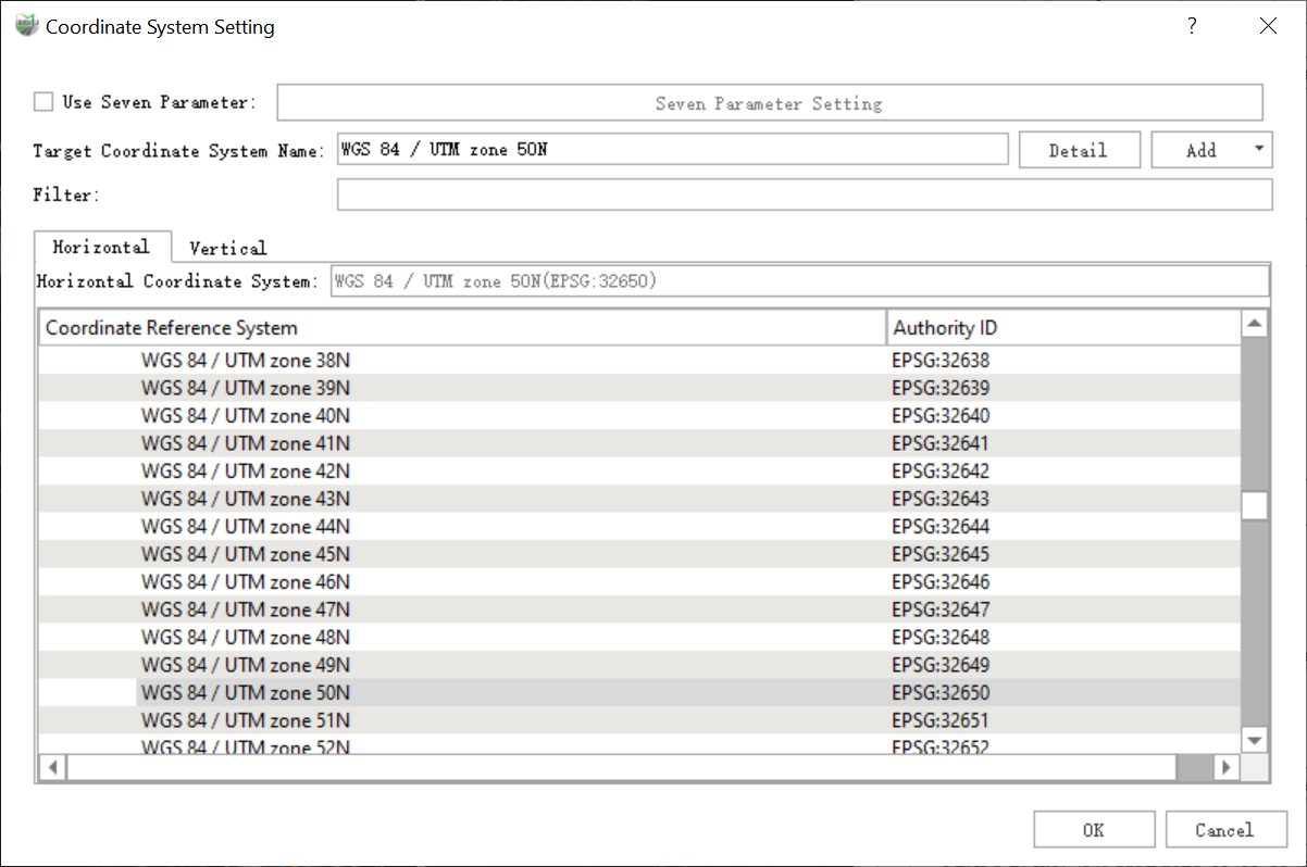
Coordinate System Setting
- Use Seven Parameter: Use seven-parameter transformation. Click the seven parameter setting button to define the seven parameters.
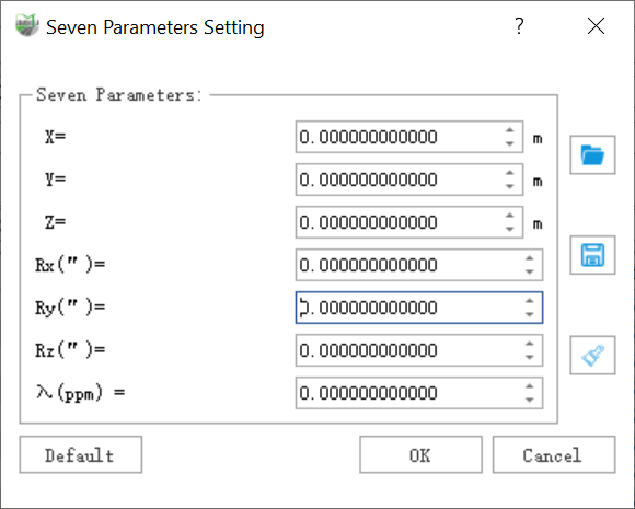
Seven Parameter Setting
- Target Coordinate System: Displays the currently selected coordinate system. You can click the Details button to view the coordinate system information in the pop-up dialog box, or you can click the Add button to add a projected coordinate system.
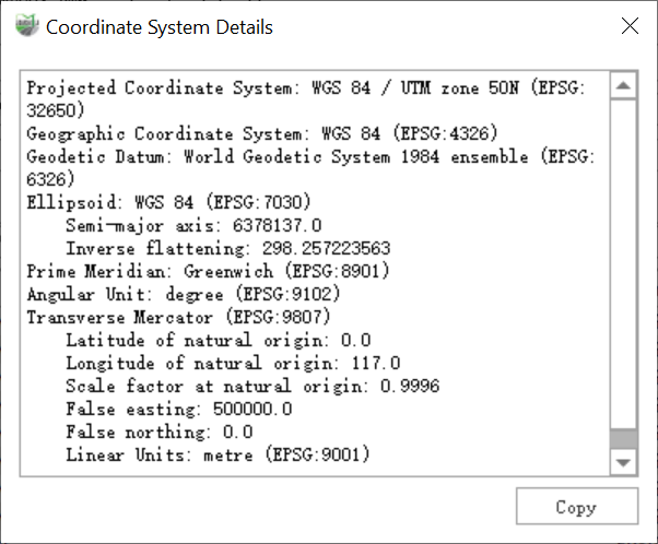
Coordinate System Details
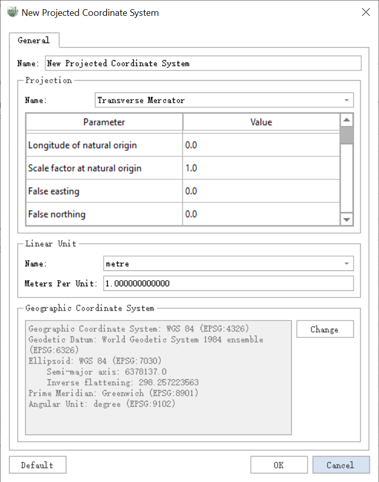
New Projected Coordinate System
- Filter: Select the coordinate system of the reprojection. By entering the keyword of the coordinate system,users can auicklv filter out the target coordinate system from the coordinate series table.
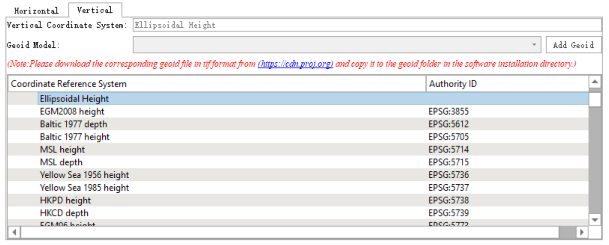
If users need to convert the vertical coordinate system, please follow the prompts to download the Geoid Model.
Vertical Coordinate System:
- Laser Setting:
- Georeference By Segment Table: Only the point cloud data corresponding to the segmented trajectories in the Trajectory Segmentation Table are processed.
- Generate Distance Attribute: Check this option to independently generate a document containing the point cloud distance attribute.
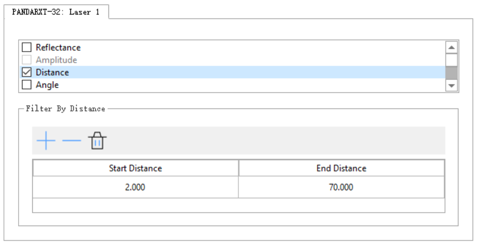
- Filter: The filtering conditions used in point cloud raw data processing. Checking multiple filter conditions at the same time will perform intersection filtering.
LiMobile require distance filtering. The recommended parameter settings are as follows.
Distance_Filter
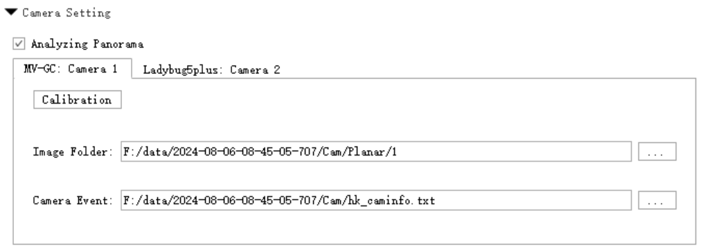
Camera Setting:
- Analyzing Panorama: Check Analyzing Panorama and perform the Georeference data processing step. The software will analyze the panoramic photos in parallel while solving the point cloud. The original *.pgr format data of the panoramic image will be converted into *.jpg format file, used for overlay display and coloring of point clouds and panoramic images.
- Analyzing Planar: Check Analyzing Planar and perform the Georeference data processing step. The software will analyze the planar photos.
Mask Removal: Check Mask Removal and perform the Georeference data processing step. The software will automatically parse the panoramic image and perform intelligent masking processing.

Camera Settings
If this step is not checked, but you still find that the panoramic image data format conversion needs to be completed after solving the point cloud, you can click Analyze Panorama button in the Tools panel for separate processing.
If this step is not checked, but you still find that the planar image data format conversion needs to be completed after solving the point cloud, you can click Analyze Planar button in the Tools panel.
If the mask removal feature is used, please switch to the Colorization Settings interface, check the Mask Path, and specify the mask file.
Planar Camera:
Calibration: The camera's calibration and placement data is imported from the calibration file. Under normal circumstances, users do not need to modify it.DeltaX, Y, Z represent the coordinate translation amount, Delta Roll, Pitch, Heading represent the angular rotation amount.
Image folder: *.jpg format plane image original data directory location.
Camera Event: Folder where camera file(* txt) stored. Camera file records exposure position and attitue.
Configure Planar Camera Raw Data
- Panoramic Camera:
- Calibration: The camera's calibration and placement data is imported from the calibration file. Under normal circumstances, users do not need to modify it.DeltaX, Y, Z represent the coordinate translation amount, Delta Roll, Pitch, Heading represent the angular rotation amount.
- Image folder: *.pgr format panoramic image source data directory.
- Camera Event: hk_caminfo.txt camera file path. The camera file contains the position and attitude information of the camera at the time of exposure. It is empty before analyzing Panorama.
- Thinning By Distance: thin out the analyzed photos according to the distance interval taken by the camera.
- Resolution: The software supports three resolutions: 8192*4096, 4096*2048, and 2048*1024.
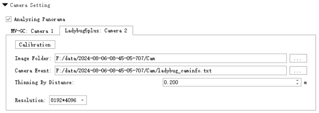
Configure Panorama Camera Raw Data
LiMobile equipment needs to use the default 8192*4096 resolution for calculation.
Advance Setting:
Usage scenario: This option is only available for M2 vehicle mounted data collection projects, while M1 vehicles with a single laser do not have this option.Vehicle mounted SLAM point cloud calculation is used to assist in the calculation of point clouds for integrated navigation. In response to the problem of insufficient accuracy in integrated navigation calculation caused by GNSS signal obstruction environments such as urban canyons, dense tree lined roads, and underground parking lots, SLAM and integrated navigation pose fusion algorithm are adopted to optimize the pose calculation accuracy in satellite signal obstruction environments, thereby improving the accuracy of point cloud calculation. It should be noted that SLAM only optimizes the trajectory segments selected by the user and automatically detects low-quality trajectory segments after trajectory calculation. Users can add or delete other low-quality trajectory segments based on this.
Attention: The accuracy of SLAM is greatly affected by environmental features. In environments with sparse features or a large number of dynamic targets, it is easy to encounter problems such as pose estimation drift or error accumulation. Therefore, it is recommended to avoid selecting certain open scenes (such as highways, elevated bridges, etc.) for calculation. If the engineering collection scene is completely open, it is not recommended to check the SLAM option, otherwise it may reduce the accuracy of point cloud calculation. The SLAM algorithm has a high demand for computing resources, especially in large-scale environments where real-time mapping and localization have a high computational complexity, which may affect the solution speed.
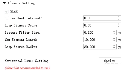
Advance Setting
SLAM: Check SLAM to display the parameter list related to SLAM calculation.
Parameter Description:
- Spline Knot Interval: Default is 0.05 seconds. The minimum time interval for trajectory optimization. The node interval is inversely proportional to processing speed.
- Loop Fitness Score: Default is 0.3 (input range: 0-1). The closed-loop score is used for revisiting scene judgment, with a default of 0.3 that is suitable for most scenes. The higher the closed-loop score, the stricter the criteria for revisiting scene judgment.
- Feature Filter Size: Default is 0.2, suitable for most scenarios. For weak-feature environments, such as underground pipelines or tunnels, it can be set to 0.1 or 0.05. Smaller feature filter sizes result in slower SLAM operation speeds.
- Max Segment Length: Default is 10.0 meters. The segment length of point clouds during loop closure detection. The segment length affects point cloud matching performance and can be adjusted based on vehicle speed and scene conditions. Segment length is inversely proportional to matching performance.
- Loop Search Radius: Default is 20.0 meters.The radius of loop search, the larger the search radius, the more candidate valid loops there will be, which will increase the computational load and slow down the running speed.
Horizontal Laser Settings: Click the option to open the horizontal LiDAR settings interface. When checked, point clouds will be generated from the SLAM LiDAR during calculation.
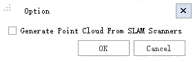
Horizontal Laser Settings
4.Strip Adjust Parameter Settings
The user needs to switch the Settings dialog box to the Strip Adjust tab bar.
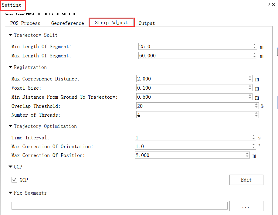
Setting_Strip Adjust
Parameter Description
Trajectory Split:
- Min Length of Segment: The minimum length of the track segment result. It is recommended to set the default value.
- Max Length of Segment: The maximum length of the track segment result. It is recommended to set the default value.
It can be adjusted according to the size of the collection area, the open area can be appropriately enlarged, and the shaded area should be reduced. Segmented point cloud is based on trajectory segmentation and provides matching point cloud for segment matching.
Registration:
- Max Correspond Distance: Matched pairs whose distance is greater than this value do not participate in the adjustment. It is recommended to set the default value.
- Voxel Size:In the matching process, set the voxelization sampling interval for matching point clouds. Setting it too large may cause the disappearance of key points, while setting it too small results in a large computational load. It is recommended to use the default settings.
- Min Distance from Ground to Trajectory: Ground points with a distance from the track height less than this value will be filtered. It is recommended to set the default value.
- Overlap Threshold: Matching pairs with overlap less than the threshold will be filtered. It is recommended to set the default value.
- Number of Threads: Match the number of threads, which is related to the computer configuration. It is recommended to follow the default. Segment matching performs relative splicing based on the revisited endpoint cloud, which provides matching constraint information for the subsequent SPLINE overall adjustment optimization, which directly affects the final splicing effect.
SpLine Optimization:
- Time Interval: SPLINE node time interval, the smaller the interval, the finer the pose correction and the greater the calculation amount. It is recommended to set the default value.
- Max Correction of Position: The maximum correction amount of SPLINE node position. It is recommended to set the default value.
- Max Correction of Orientation: The SPLINE overall adjustment takes the trajectory pose corresponding to the SPLINE node as the basic adjustment unit, and adjusts the trajectory pose correction based on the SPLINE assumption to perform adjustment optimization to achieve the corrected trajectory pose splicing point cloud and guarantee the corrected trajectory pose smooth and specific effects. The maximum amount of correction for the attitude of SPLINE nodes. It is recommended to set the default value.
GCP
Check GCP to make the control points participate in the flight belt adjustment. The user needs to click the Edit button to proceed GCP Edit.
Fix Segments
Import the trajectory segment file corresponding to the current project. This file is generated by selecting part of the trajectory through the trajectory segmentation function. The selected trajectory means that these data will not be processed during splicing.
5.Output Parameter Settings
The user needs to switch the Setting dialog box to the Output tab bar.
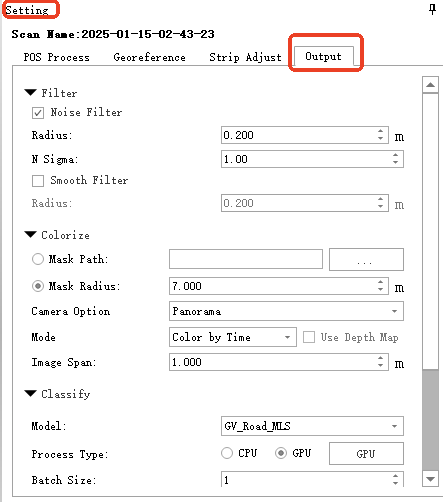
Output
Parameter Description
Filter
- Noise Filter: When checked, set the standard deviation multiplier. Points exceeding the set multiple of the standard deviation are considered noise and will be filtered out. Generally, a smaller value results in better noise removal, but setting it too small may over-filter, leading to abnormal point clouds.
- Smooth Filter: Default value is 0.2. Primarily used to thin out point clouds. If the value is set too high, it may cause deformation of features or abnormal point clouds.
Colorize
- Mask Path: Using a mask file offers a more accurate masking area compared to the radius mode.
- Mask Radius:Setting a radius offers an approximate masking area.
- Camera Option: The software supports Panorama and Planar color rendering respectively.
- Mode:
- Color by Time: Select photos recently for coloring based on time.
- Color by Distance: Select photos based on the closest distance for coloring.
- Optimize Color Discrepancy: Optimize color blending by prioritizing color similarity in image selection, reducing overall color aberration. Note: Enabling this feature may introduce a minor blurring artifact. Disable if sharpness is preferred.
- Use depth map: Using depth map can largely avoid wrong color assignment, such as street lights being assigned to the ground behind. However, this option will add a certain amount of color assignment time, and only supports the distance color assignment mode of panoramic images.
- Blend: Used to smooth the seams in the colorized image, resulting in a more natural transition.
- Optimize Sky-coloured Points: This is used to improve instances where sky colors are incorrectly applied to trees. This option is more time-consuming and only supports colorization based on panoramic images.
- Image Span: This parameter is used to thin out photos. The larger the spacing setting, the fewer photos will be involved in coloring.
Classify
- Model: For the models used for deep learning classification, the software mentions the following models by default: GV_Road_MLS, GV_Indoor_HLS, GV_Park_HLS, GV_Forest_HLS,GV_Garage_HLS, and GV_Railway. The default GV_Road_MLS model can be used for LiMobile data process.
- Process Type: There are two processing modes: GPU and CPU. The default is CPU mode. If the computer graphics card has higher performance, you can switch to GPU mode by yourself. The GPU efficiency will be about twice as high as that of the CPU. If the computer has multiple graphics cards , you can choose the appropriate graphics card by yourself. It is strongly recommended to use NVIDIA graphics cards for GPU mode classification. The user can click the GPU button to set the processing mode in the pop-up Process Settings dialog box.
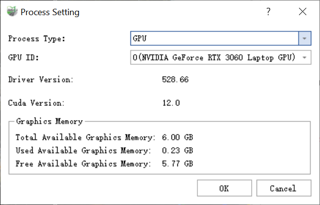
Process Settings
- Batch Size: indicates the number of point cloud samples processed each time. The higher the computer memory and video memory, the larger the value that can be set and the faster the overall processing speed. The software has set a default value based on computer performance. It is recommended that users change the value by themselves to no more than 8.
Advance Setting
- Block Length: The point cloud is processed into blocks according to the set length. The larger the chunks, the higher the memory usage.
- Buffer: The length of the overlapping portion of adjacent blocks.
Classify Mapping: Category mapping: Map categories to corresponding category labels. Click the Set button, and the user can set the categories and labels in the Classification dialog box according to needs. For example: the corresponding category ID of Unclassified is 1.
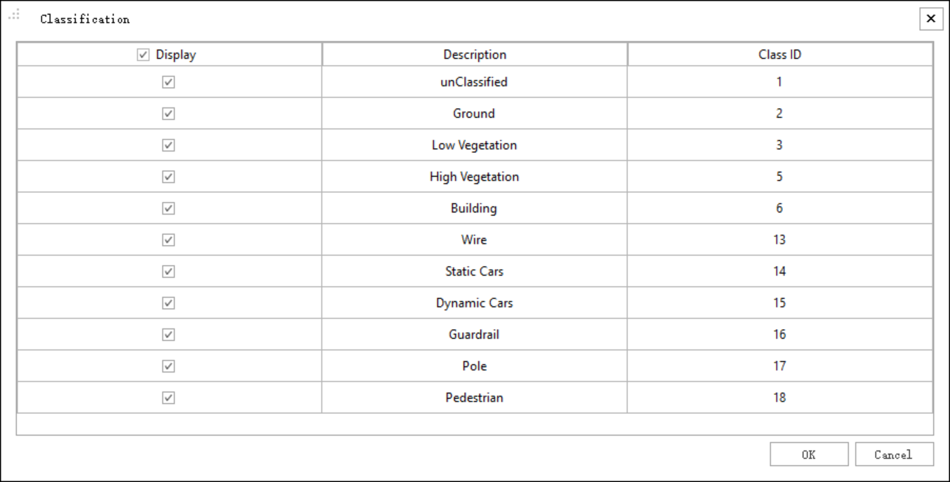
Classfication
Ground Point Optimize: checked by default. During the deep learning classification process, ground optimization is performed to improve the classification accuracy of ground points. For specific parameter descriptions, please refer to Classify Ground Points.
6.Parameter Setting Confirmation
Please note that after users set parameters, they need to click the OK button for the settings to take effect. If you perform batch data calculation for multiple *.liscan projects, users can click the Apply to all button, and the common parameter settings will be extended to all *.liscan projects in the directory tree.