GCP Adjustment
Steps
1.Data preparation: Data preparation includes the following two aspects
1.1. Source data: It contains the original point cloud to be corrected and the corresponding trajectory file. If there is an image file during the data calculation, the image data is also required. Among them, LiDAR360MLS software can be used to directly open the .ligeo project file solved by Ligeo, or you can also refer to New Project to configure point cloud, trajectory, Image, to create a new .LiMMP project.
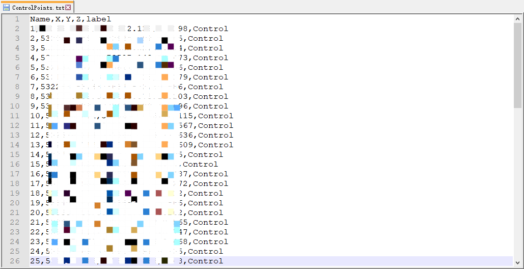
1.2. Control point file: The control point file needs to be organized into a .txt, which includes five columns of information: point name, X, Y, Z, label. Among them, the first four columns can generally be obtained when external dots are made. The label needs to use Control/Check to distinguish whether it is a control point or a check point.
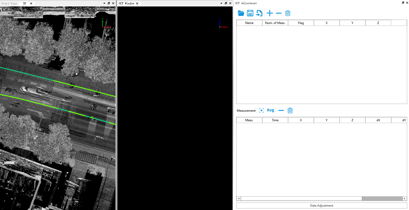
2.Click GCP Adjustment![]() button to activate this function, the control point correction dialog box will appear on the right side of the main page, and the GCP window will appear at the same time.
button to activate this function, the control point correction dialog box will appear on the right side of the main page, and the GCP window will appear at the same time.
3.Import external control point file: Click Import![]() button to import the control point TXT file prepared in step.
button to import the control point TXT file prepared in step.
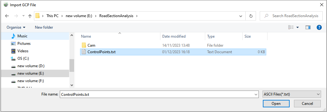
Select the file to import, and you will be prompted to select the corresponding column name. You can select and match the column according to the actual situation of the control point file.
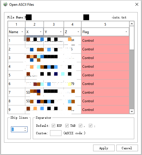
4.If the control point file is not prepared in the early stage, but the control point information is known, you can add different control points by clicking on the ground control point. Click the ![]() button in the upper half of the Control Point Alignment window, the Click Ground Control Point dialog box will appear:
button in the upper half of the Control Point Alignment window, the Click Ground Control Point dialog box will appear:
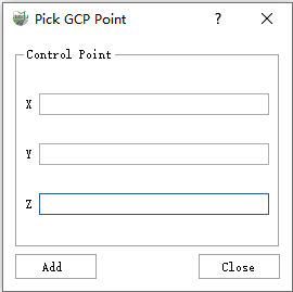
By entering the control point information in the text boxes corresponding to XYZ, and clicking the Add button, you can add a new control point. If there is no RTK control point collected in the field, but the collected data has poor accuracy on a certain channel, you can click on the corresponding point cloud of the flight belt in the 3D window to collect the feature point coordinates of the point cloud in the reverse direction as the reference control point.
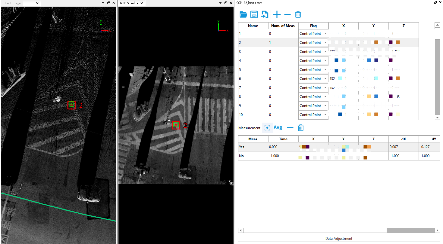
5.After the control point file is imported normally, you can see that the software interface displays the following contents:
(1) 3D window: The data from the point cloud file where the first control point is located will be displayed by default. In the upper part of the control point correction window, click on any control point to control the display the section of the point cloud where the current control point is located in the 3D window.
(2) The GCP window displays the currently selected control point and the point cloud data of the current air strip within a certain slice range. In the upper part of the control point correction window, click on any control point to control the data within the single air strip slice range in the current window.
(3) Control point guide dialog:
(3.1) The upper part shows the imported point-by-point information:
- Name: The imported control point name.
- Num. of Meas.: The current control point that can control several air strips, that is, the current control point in the lower half has been punctured correspondingly on several air strips.
- Flag: The type of control point, Control Point indicates that the current point is the control point during the deviation correction process; Check Point indicates that the current point is the check point during the deviation correction process.
- X: East coordinate of control point coordinates.
- Y: North coordinate of the control point file.
- Z: The elevation value of the control point.
(3.2) The lower part displays the information about each control corresponding point to be punctured, click any record, and then use the mouse to click the point of the point cloud corresponding to the current control point in the GCP window with the left mouse button to puncture:
- Meas.: No means that the flight zone is not constrained by the corresponding control point, Yes means the flight zone is constrained by the current control point.
- Time: The collection time of the current puncture point position.
- X: The east coordinate of the point cloud representing the current puncture point position.
- Y: The north coordinate of the point cloud representing the current puncture point position.
- Z: The point cloud elevation value representing the current puncture point position.
- dx: The offset between the point cloud and the east coordinate of the current control point.
- dY: The offset of the point cloud from the north coordinate of the current control point.
- dZ: The coordinate offset between the point cloud and the current control point elevation.
6.When all the punctures corresponding to all the control points are completed, click Save File![]() button to export the GCP control point information, the exported xml file can not only continue to be loaded later
button to export the GCP control point information, the exported xml file can not only continue to be loaded later ![]() and the only current function continues to be modified and used, and this file is also used as the control point file information in the splicing process in the StripAdjust function.
and the only current function continues to be modified and used, and this file is also used as the control point file information in the splicing process in the StripAdjust function.
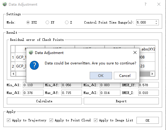
7.Click Data Adjustment, and the Data Adjustment dialog box will pop up. In this dialog box, set the correction mode, perform the correction calculation, and view the checkpoint residuals. Click the Calculate button to calculate the control point correction parameters according to the puncture point information.
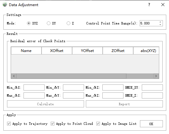
Parameter Description:
- Setting Mode: The mode used to set the skew correction.
- XYZ: Represents correcting coordinates in three directions of XYZ at the same time.
- XY: Represents only correct coordinates in both XY directions.
- Z: Means to correct only the value in the Z direction.
- Control time range (seconds): Represents the sampling interval by time.
- Result: To calculate the correction parameters of the control point, and check the correction accuracy of the set check point.
- Apply: After the correction parameters are confirmed to be correct, you can click the OK button to apply the results to the selected data type. It is recommended to select all of them here. At the same time, the image data must be set when creating a new project. Otherwise, it will not modify the image information, which may cause the point cloud and the image to be misaligned after the offset correction.
Note: This step will rewrite the original data, please make sure that there is no problem in the parameter calculation before applying it.
