Merge To Lane
Strongly advised that before using this feature, please check and correct the geometry of line vectors to ensure correct merging, and that there is no error in the geometry of the merged lane lines.
Steps
1.In the Road Vector Detection panel, click the Merge To Lane ![]() button.
button.
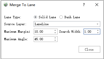
2.The Merge To Lane dialog box pops up:
Dialog Box
Parameter Description:
Lane Type: Set the type of lane lines to be generated
Source Layer: The source of the lines to be merged. Only the line vectors in the source layer can be selected and merged.
Maximum Margin: The maximum gap for sequential connection. Lines with a gap larger than this value will not be merged, refer to the example diagram.
Search Width: Search for the next line within a certain width on the left and right along the forward direction of the line, refer to the example diagram.
Maximum Angle: The maximum angle for sequential connection. Lines with an angle larger than this value will not be merged, refer to the example diagram.
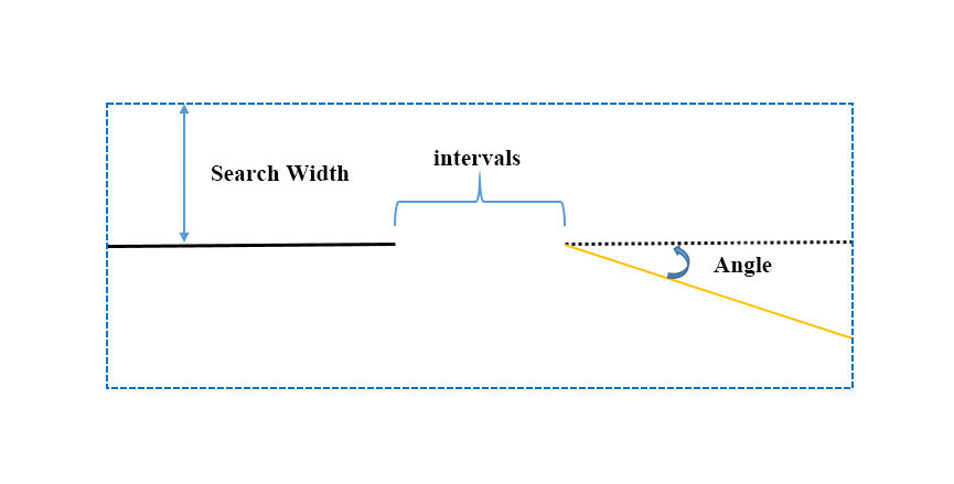
Schematic diagram, the black solid line is the first line; the yellow solid line is the second line
3.Window tips:
| Shortcut Key Name | Function |
|---|---|
| Space | Interrupt merging |
| Enter | End merging |
| C | Switch between automatic/manual mode |
| H | Close/Open the top left corner prompt |
| Current model | Current drawing mode |
| Right mouse button | Retract a single node (only effective after the interruption, invalid during growth) |
This function provides two modes, one is automatic mode, which automatically merges forward by selecting a vector line. The other is manual mode, where line nodes are added by clicking the left mouse button. The two modes can be switched by pressing C during the drawing process.
Solid Line Merge
Choose a solid line as the lane line type.
1.Select the first line. Note that when selecting the first line, the mouse selection position determines the direction of the line. The principle of selection is that the mouse selection position is the tail end of the first line.
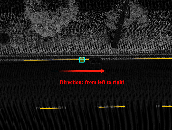
Schematic diagram, if the mouse selects the right side of the line, then the right side is the tail end
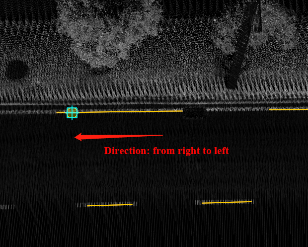
Schematic diagram, if the mouse selects the left side of the line, then the left side is the tail end
2.Select the first line to determine the direction of the merged line, click with the left mouse button, and select the first line according to the principle above.
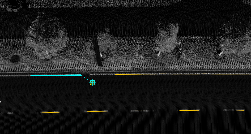
Select the first line
3.Select the second line. You can start automatic forward merging by clicking on any position of the second line with the left mouse button until the conditions are not met and the auto-merge is automatically terminated.
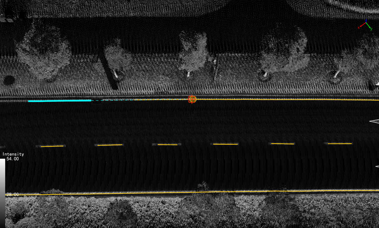
Select the second line
4.Interruption Conditions
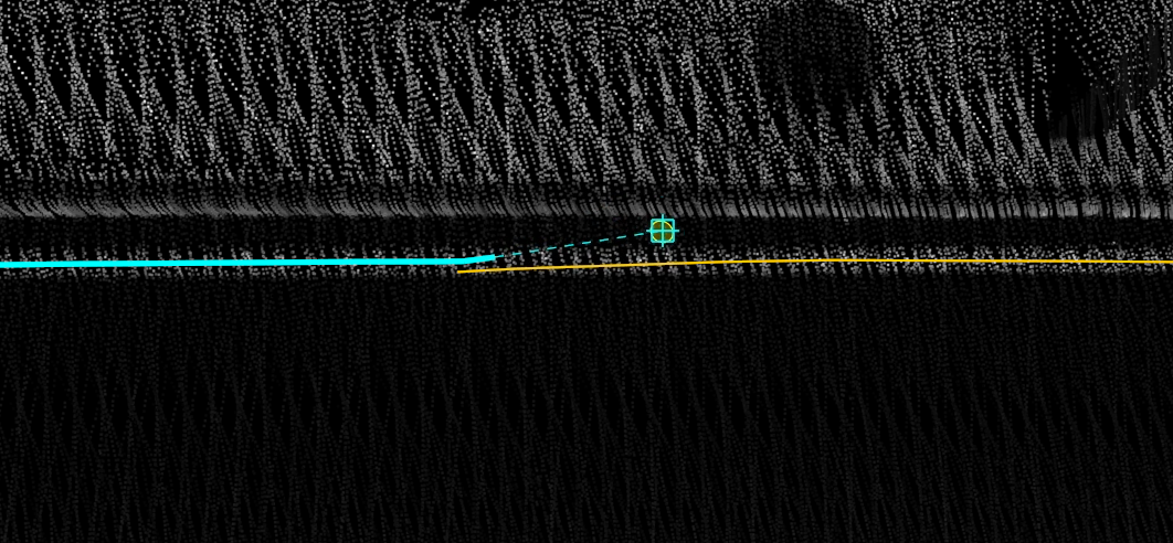
Interruption condition: Backfolding occurs
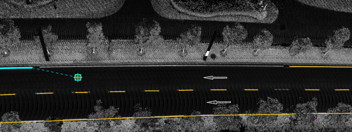
Interruption condition: Maximum gap exceeded
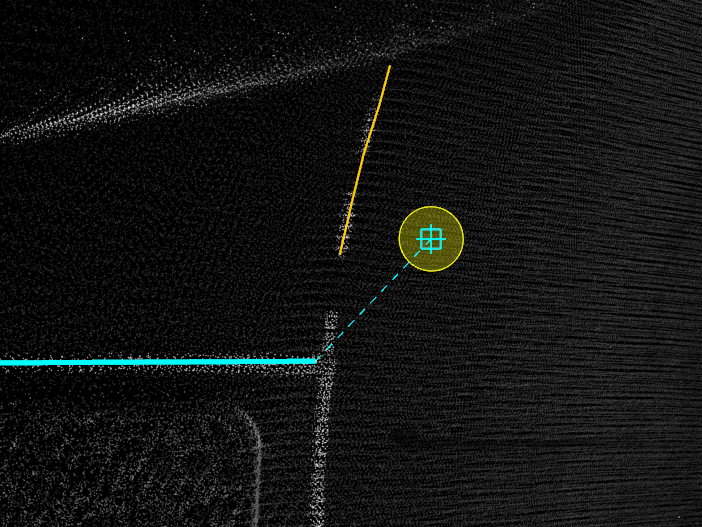
Interruption condition: Maximum angle exceeded
5.After the interruption, detect again:
- Automatic mode: After the interruption is generated in the above situation, the forward direction of the line is known at this time, so just repeat step 2, and re-select the next line to start the automatic merge again.
If the reason for the interruption is back folding, to prevent the final line from having back folding, it is strongly recommended to withdraw the function first, adjust the line geometry, and eliminate the back folding.
- Manual mode: After the interruption is generated in the above situation, if the next line is too far from the current line, or the angle is too large, and the direct connection will not conform to the actual scene, you need to manually add points. Press the C key to switch to manual mode, and add points one by one with the mouse.
Switch back to automatic mode:
Double-click to end manual mode, and automatically switch to automatic mode;
Press the C key to switch.
After the interruption, you can use the right mouse button to retract, to adjust the shape.
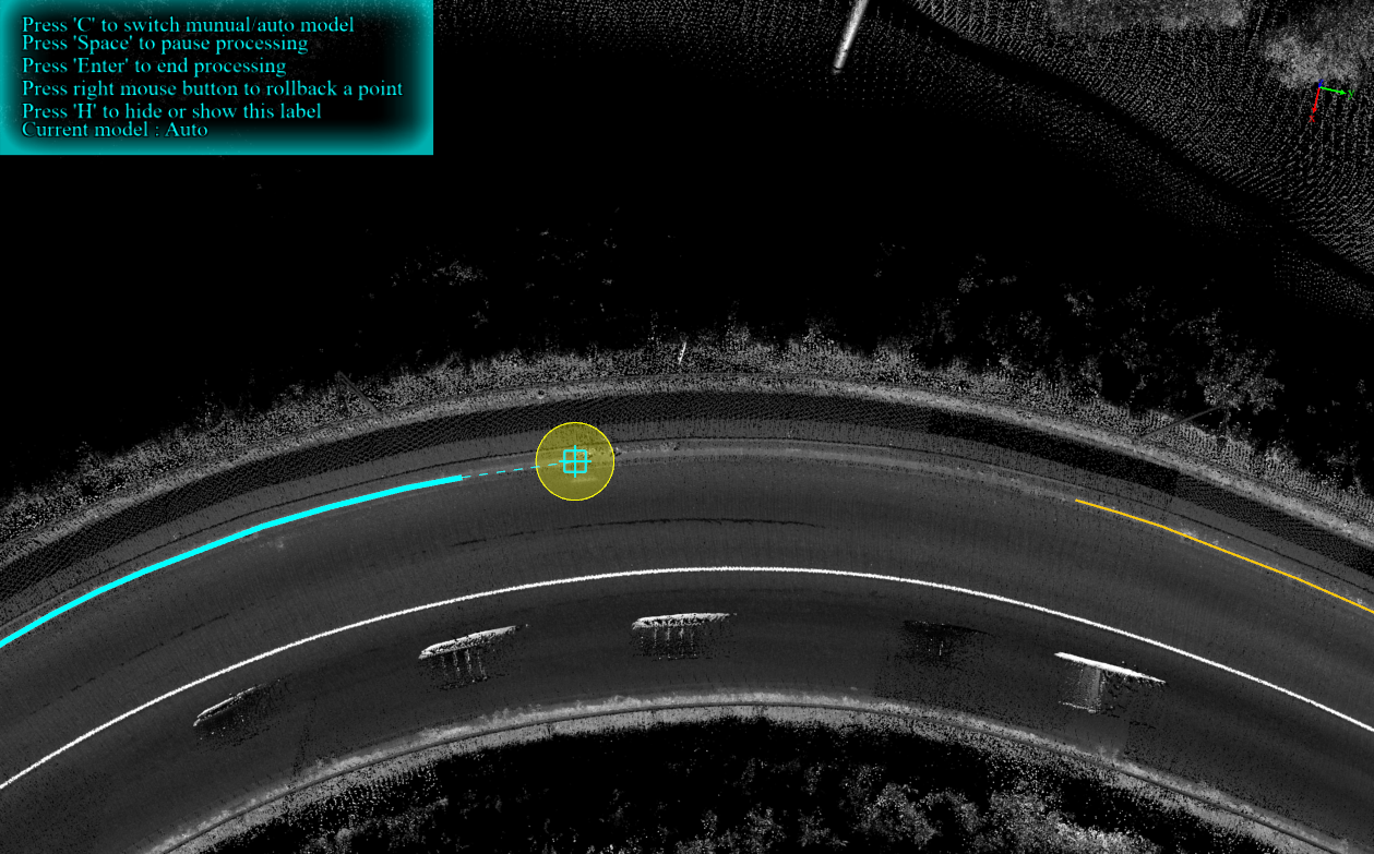
Scenes that need to manually add points
6.After the merge (or drawing) is completed and the shape is acceptable, press the Enter key (Enter, confirmation key) in automatic mode to complete the merge of the current lane solid line.
Dashed Line Merge
Choose the dashed line as the lane line type.
1.Select the first vector line, refer to solid line merge.
2.Select the second vector line, refer to solid line merge.
3.Interruption conditions, refer to solid line merge.
4.In the case of interruption, if you switch to manual mode, unlike the solid line merge which adds points one by one, the dashed line merge needs to add two points at the same time to add a dashed line segment.
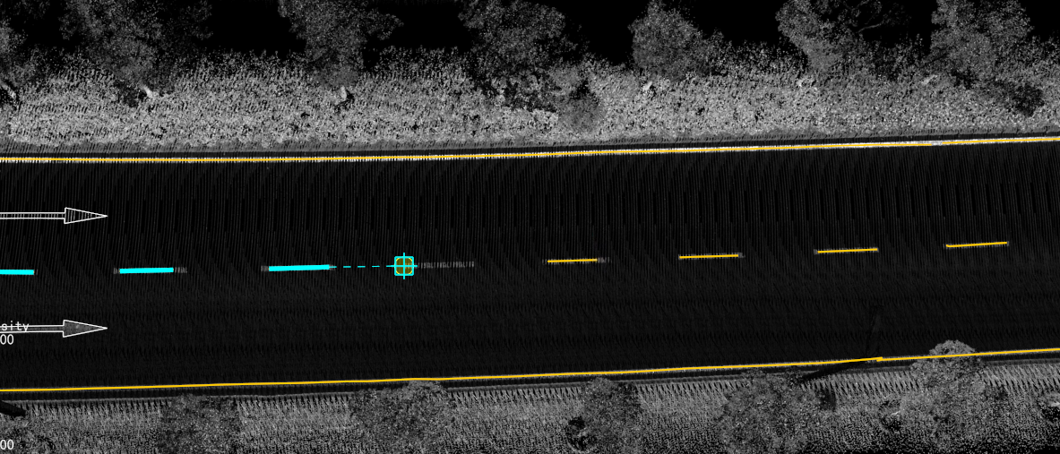
Left-click with the mouse, manually add the starting point of the dashed line segment
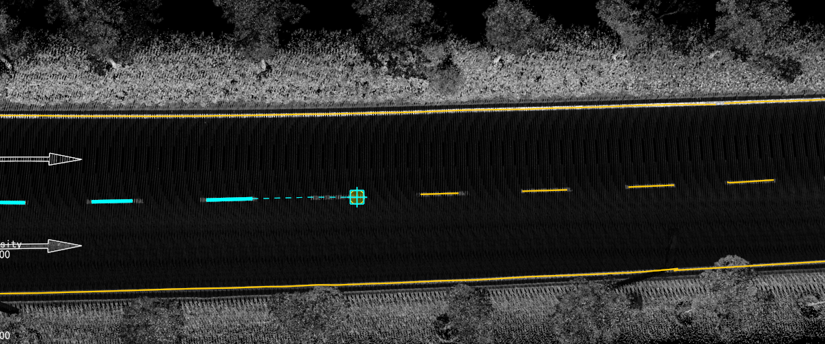
Left-click with the mouse, manually add the endpoint of the dashed line segment
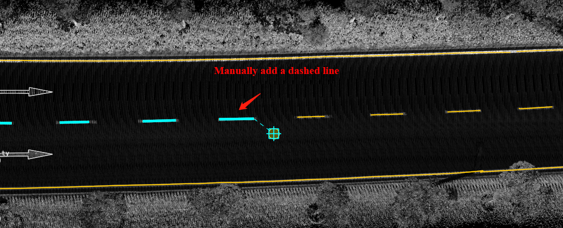
Manual adding effect
5.Detect again after the interruption, refer to the solid line merge.
6.After the merge, refer to the solid line merge.