Aspect
Function Description: Derives the aspect for each cell from the raster surface.
How It Works
The Aspect tool identifies the direction the downhill slope faces. The values of each cell in the output raster indicate the compass direction the surface faces at that location. It is measured clockwise in degrees from 0 (due north) to 360 (again due north), coming full circle. Flat areas having no downslope direction are given a value of -1.
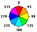
Aspect directions
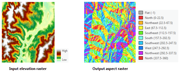
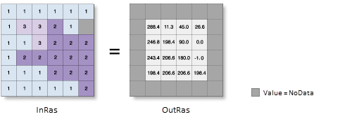
The following images show an input elevation dataset and the output aspect raster.
Inputs and Outputs
Aspect Algorithm
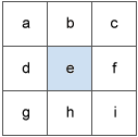
A moving 3x3 window accesses each cell in the input raster. For each cell at the center of the window, its aspect value is calculated using an algorithm that incorporates the values of its eight neighboring cells. These cells are labeled with letters a through i, where e represents the cell for which the aspect is being calculated.
Surface window
The rate of change in the x direction for cell e is calculated with the following algorithm:
[dz/dx] = ((c + 2f + i)*4/wght1 - (a + 2d + g)*4/wght2) / 8
where:
wght1 and wght2 are the horizontal weighted counts of valid cells.
For instance:
- if c, f, and i all have valid values, wght1 = (1+2*1+1) = 4.
- if i is NoData, wght1 = (1+2*1+0) = 3.
- if f is NoData, wght1 = (1+2*0+1) = 2.
Similar logic applies to wght2, except the neighbor locations are a, d, and g.
The rate of change in the y direction for cell e is calculated with the following algorithm:
[dz/dy] = ((g + 2h + i)*4/wght3 - (a + 2b + c)*4/wght4 ) / 8
where:
wght3 and wght4 are the same concept as in the [dz/dx] computation.
Taking the rate of change in both the x and y direction for cell e, aspect is calculated using the following:
aspect = 57.29578 * atan2 ([dz/dy], -[dz/dx])
The aspect value is then converted to compass direction values (0-360 degrees), according to the following rule:
if aspect < 0
    cell = 90.0 - aspect
else if aspect > 90.0
    cell = 360.0 - aspect + 90.0
else
    cell = 90.0 - aspect
Calculation Example
In the example, the planar aspect value of the center cell within the moving window is calculated.
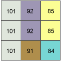
Aspect Calculation Example
he rate of change in the x direction for the center cell e is:
[dz/dx] = ((c + 2f + i)*4/wght1 - (a + 2d + g)*4/wght2) / 8
        = ((85 + 170 + 84)*4/(1+2+1) - (101 + 202 + 101)*4/(1+2+1)) / 8
        = -8.125
The rate of change in the y direction for cell e is:
[dz/dy] = ((g + 2h + i)*4/wght3 - (a + 2b + c)*4/wght4) / 8
        = ((101 + 182 + 84)*4/(1+2+1) - (101 + 184 + 85)*4/(1+2+1)) / 8
        = -0.375
The aspect is calculated as:
aspect = 57.29578 * atan2 ([dz/dy], -[dz/dx])
       = 57.29578 * atan2 (-0.375, 8.125)
       = -2.64
Since the calculated value is less than zero, the final rule will be applied as:
cell = 90.0 - aspect
     = 90 - (-2.64)
     = 90 + 2.64
     = 92.64
The value of 92.64 for the center cell e indicates that its aspect is in the easterly direction.
Data Description
Input and Output Relationship
Aspect Calculation Input and Output Relationship
This tool processes the data using a moving 3x3 cell window. If the processing cell is NoData, the output for that location will also be NoData.
The tool also requires that at least 7 of the 8 neighboring cells adjacent to the processing cell have valid values. If fewer than 7 valid cells are present, the calculation is not performed, and the output for that processing cell will be NoData.
The cells in the outermost rows and columns of the output raster will be NoData because these cells do not have enough valid neighboring cells along the boundary of the input dataset.
Aspect is represented in degrees from 0 to 360, measured clockwise with north as the reference direction.
A value of -1 for aspect will be assigned to flat (zero slope) cells in the input raster.
Steps
- Find Toolbox -> Raster Tools -> Surface Analysis -> Aspect tool, and double-click to open the tool's dialog window.
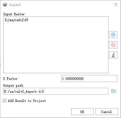
Aspect
Parameter Description:
- Input Raster: The input surface raster.
- Z Factor: The number of ground units (x, y) per surface z unit. When the z units and the x, y units of the input surface are different, the Z factor is used to adjust the z units' measurement. The Z factor is multiplied by the z values of the input surface when calculating the final output surface. If the x, y units and z units use the same measurement units, the Z factor is 1. This is the default setting. If the x, y units and z units use different measurement units, the Z factor must be set to the appropriate value, or incorrect results will occur. For example, if the z units are in feet and the x, y units are in meters, a Z factor of 0.3048 should be used to convert feet to meters (1 foot = 0.3048 meters).
- Output path: The output aspect raster. This raster is of floating-point type.
- Add Result to Project: If checked, a layer for the result data will be automatically created and added to the project.