Detect Road Side Line
Note: This function is only effective for areas with clear curbs and the curb height is above 10 cm.
Steps
1.Click the Detect Road![]() button in the Road Shape panel.
button in the Road Shape panel.
2.A Detection Settings dialog box will appear:
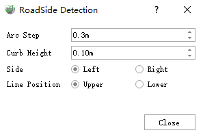
Pop up Detection Settings dialog box
Parameter Description:
Arc Step: The default is 0.3 meters, and the curb may have a larger arc. If the step length is set too large, the arc part will not fit the actual point cloud enough. It is recommended to be less than 0.3 meters, 0.1 meters above.
Curb Height: The default is 0.1. If the peripheral curb is lower than the set value, it cannot be detected. The default value is recommended.
Side: The default is the left side. It indicates which side of the straight line formed by the starting point and direction points of the point selection is located in the actual path point cloud, which is selected according to the actual situation.
Line Position: The default is upper, which means that the final generated line is located on the upper or lower edge of the curb. The upper line is calculated by adding the height of the curb to the point Z value of the lower line. Therefore, the position of the upper line can be adjusted by adjusting the height of the curb.
3.3D window tips:
| Shortcut name | Function |
|---|---|
| Space | Interrupt growth |
| Enter | Confirm growth result |
| C | Toggles between automatic/manual drawing mode |
| B | Toggles between batch or one-by-one plotting in manual mode |
| H | switch off/on the top left corner prompt |
| Current model | Current model |
| Right mouse button | Rewind node (only works after interruption, not during growth) |
Two modes are available in the curb detection function, a semi-automatic mode, where automatic detection is carried out by means of the "start point + direction" mode, and a manual mode, which follows the manual drawing mode of the "draw curb line" function. Both modes can be switched between during the drawing process by means of C.
4.The initial drawing mode is "semi-automatic". Left click to select a point on the road surface point cloud as the starting point, and then left click again to select another point on the road surface as the direction point.
Note: The clicked starting point and direction point must be clicked on the surrounding road surface. The distance between the clicked point and the actual curb point cloud is recommended to be more than 0.1 meters and within 0.5 meters.
5.Along the selected direction, automatic roadside detection starts from the starting point.
During the growth process, the center of the screen is automatically adjusted to the point currently growing; at the same time, the angle of the point cloud can be adjusted, dragged, and zoomed to view the point cloud through the left, right, and scroll wheels of the mouse.
6.Use shortcut keys for real-time road shape adjustment:
- The program is automatically interrupted due to the reasons such as low curb height, actual termination, actual interruption, etc.; if the automatic growth does not grow correctly, the user can use the Space to manually interrupt.
- After interruption, the user can right click to go back to adjust the shape.
- After interruption, operations 3 and 4 can be repeated, followed by automatic growth.
- If the point cloud is missing in a large area due to occlusion, etc., and the program cannot detect it automatically, you can switch to manual mode with C and then draw by manually clicking on the key points, and when the manual drawing is finished, you can double-click to end the current mode or switch to automatic mode with C.
7.When the growth is completed and the shape is acceptable, press the Enter(Enter, confirm key) to complete the growth of the solid line of the current lane.
Straight Road Curb
- Click the starting point and direction point
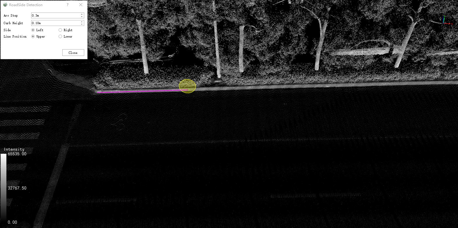
Click the starting point and direction point
- Interrupt and click again
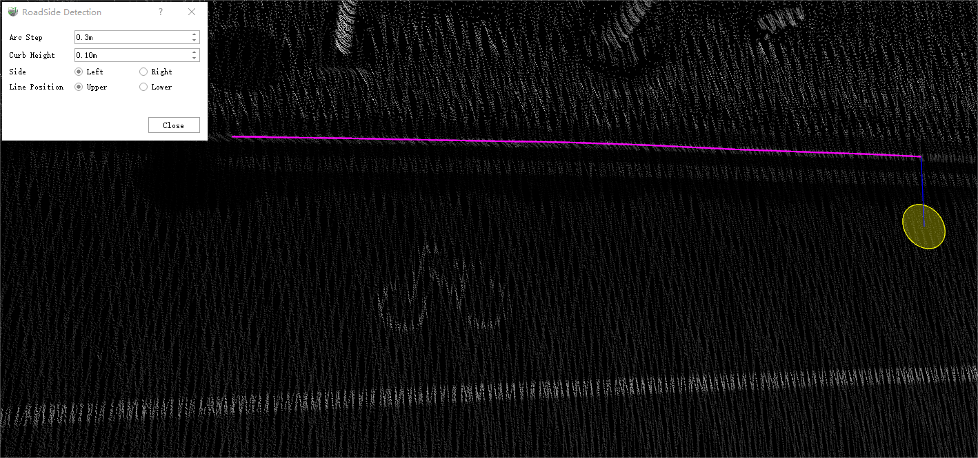
Interrupt
- Growth result
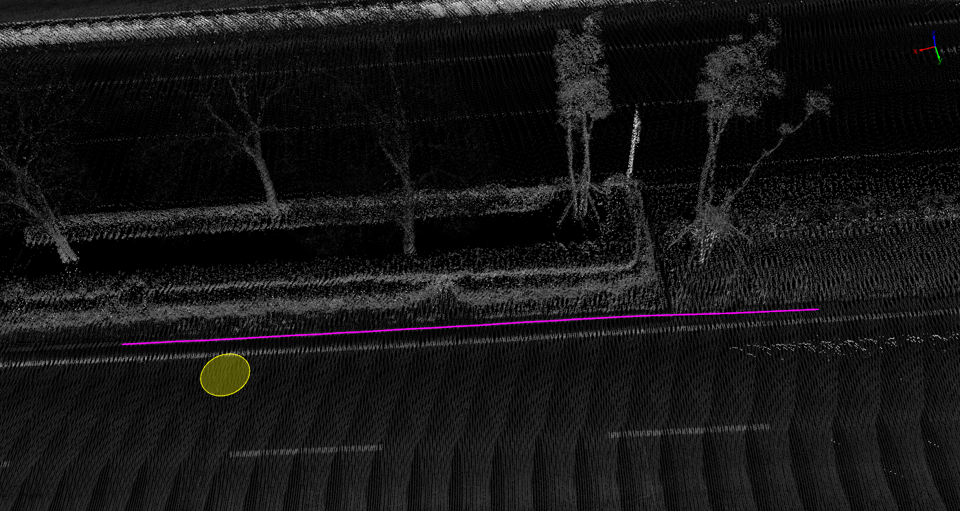
Curb growth result
Closed Round Curb
- Click the starting point and direction point
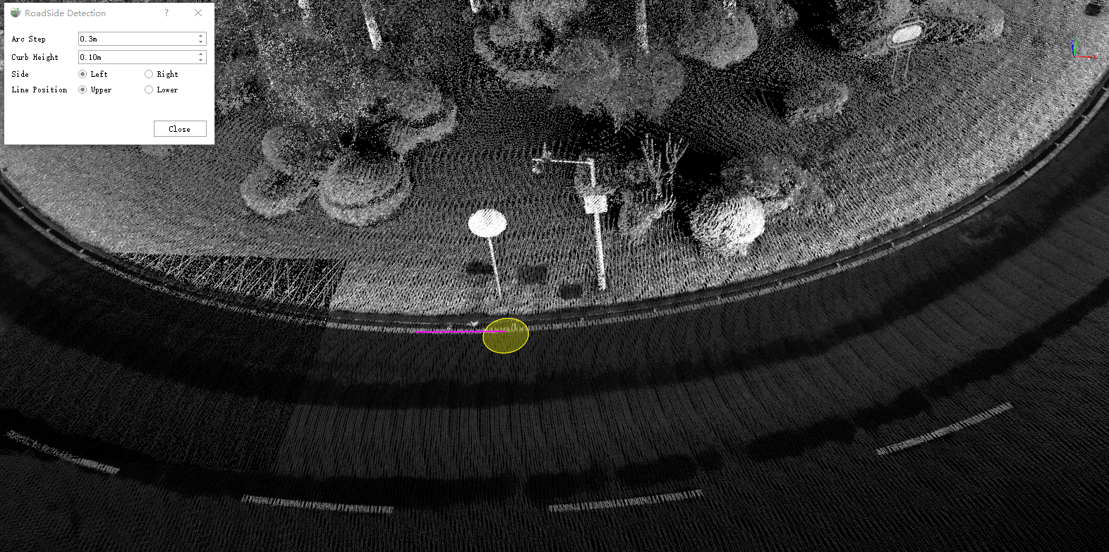
Click the starting point and direction point
- Growth result
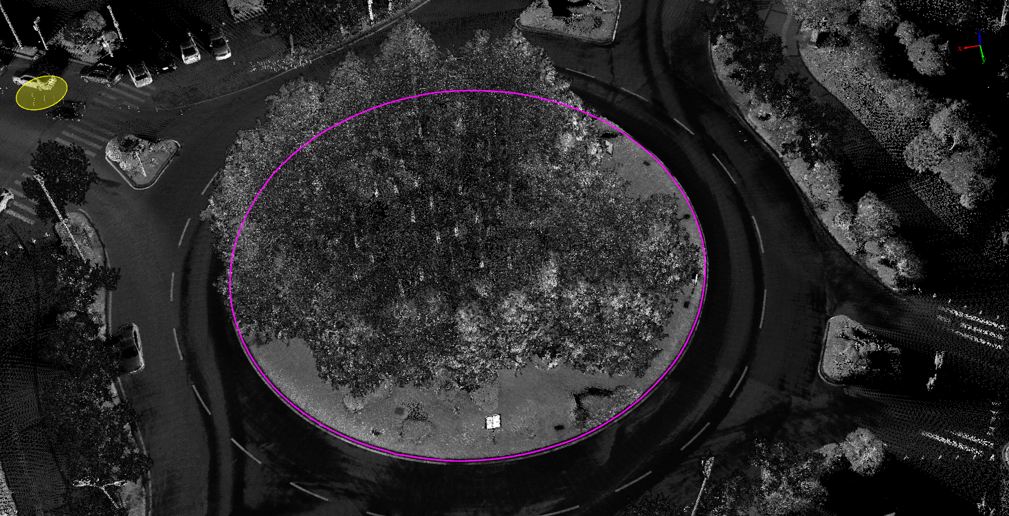
Round curb growth result