GCP Edit
Step
1.External control point file preparation: The control point file needs to be organized into a *.txt file format, which includes five columns of information: roll call, X, Y, Z, and label. The first four columns can generally be obtained when doing external points. The label needs to use control/Check to distinguish whether it is a control point or a check point.
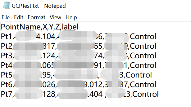
GCP File
2.Click the GCP Edit button to pop up the control point editing dialog box, and the GCP window will appear at the same time.
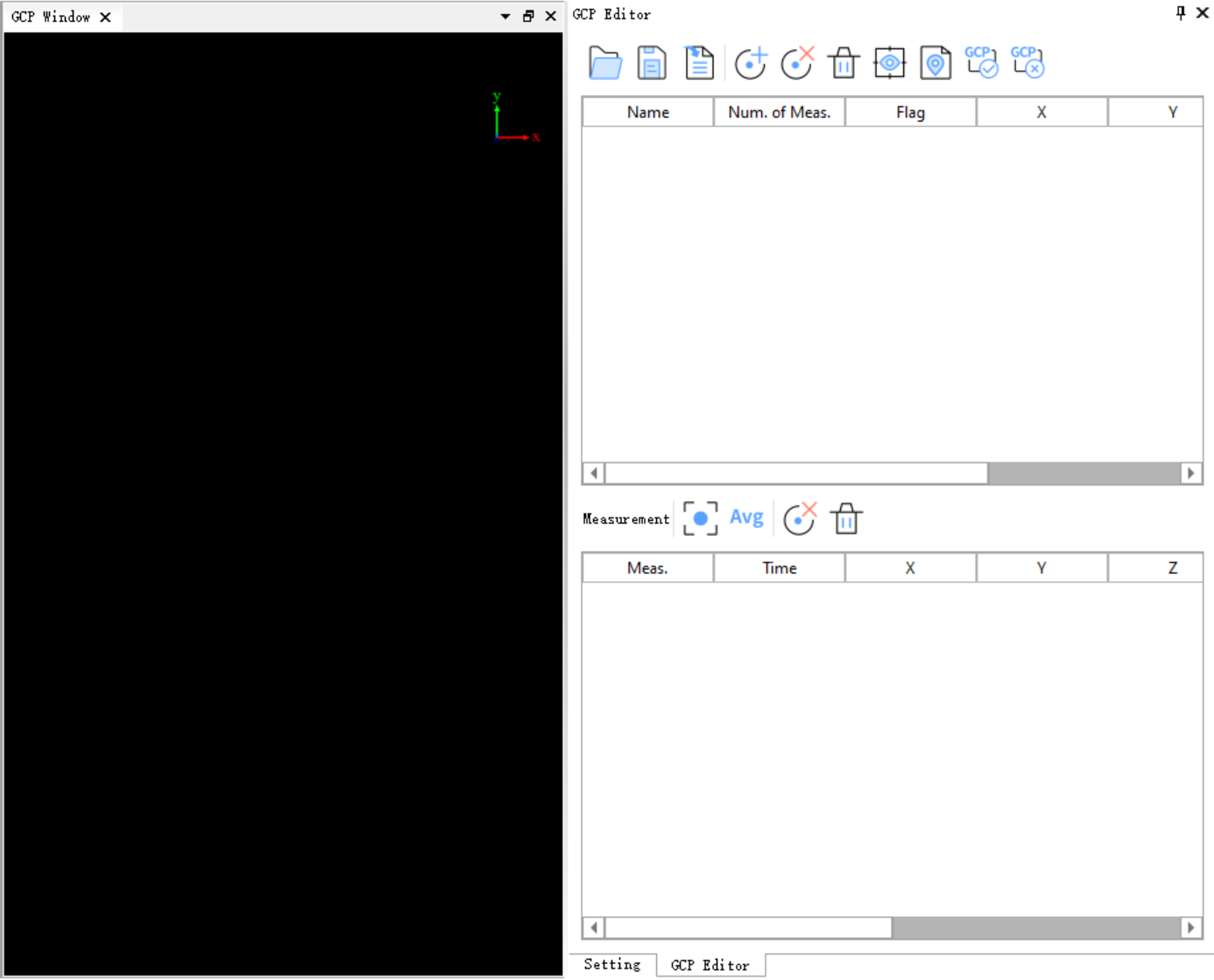
GCP Window and GCP Edit
Parameter description:
- The upper part of the GCP Edit dialog box:
- Open

- Save
- Import

- Add

- Delete

- Delete All

- View

- Report

- Save

- Cancel

- Open
- The lower part of the GCP Edit dialog box
- Set Measured Point As Reference

- Set Measured Average As Reference

- Delete Measured Point

- Delete All MeasuredPoints

- Set Measured Point As Reference
3.Import external control point files: Click Import![]() button, select the external control point file prepared in step 1 and click the Open button. After importing, the Open ASCII Files dialog box will pop up and prompt to select the corresponding column name. You can According to the actual situation of the control point file, column selection matching is performed accordingly.
button, select the external control point file prepared in step 1 and click the Open button. After importing, the Open ASCII Files dialog box will pop up and prompt to select the corresponding column name. You can According to the actual situation of the control point file, column selection matching is performed accordingly.
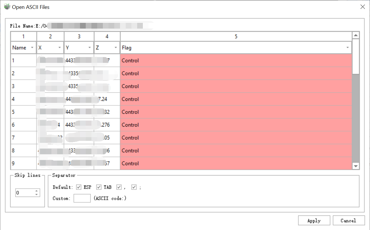
Open ASCII Files
4.If the control point file is not prepared in the early stage, but the control point information is known, you can add different control points by clicking on the ground control point.Click Add Control Point in the upper part of the GCP Edit window![]() button,the Pick GCP Point dialog box will pop up.
button,the Pick GCP Point dialog box will pop up.
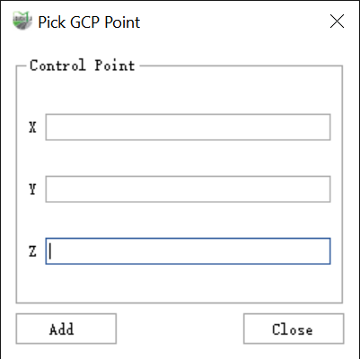
Pick GCP Point
New control points can be added by entering the control point information in the text boxes corresponding to X, Y, and Z and clicking the Add button.
If there are no RTK control points collected by the field, but the accuracy of the collected data for a certain route is poor, you can click on the corresponding reverse direction of the route in the 3D window to collect the characteristic point coordinates of the point cloud of the route as a reference control point.
5.After the control point file is imported normally, you can see that the software interface displays the following content:
3D window: The data from the point cloud file where the first control point is located will be displayed by default. In the upper part of the control point correction window, click on any control point to control the display the section of the point cloud where the current control point is located in the 3D window.
GCP window: The GCP window displays the currently selected control point and the point cloud data of the current air strip within a certain slice range. In the upper part of the control point correction window, click on any control point to control the data within the single air strip slice range in the current window.
The Upper part of the control point editing dialog box: imported control point-by-control information.
Parameter description:
- Name: The imported control point name.
- Num. of Meas.: The current control point that can control several air strips, that is, the current control point in the lower half has been punctured correspondingly on several air strips.
- Flag: The type of control point, Control Point indicates that the current point is the control point during the deviation correction process; Check Point indicates that the current point is the check point during the deviation correction process.
- X: East coordinate of control point coordinates.
- Y: North coordinate of the control point file.
- Z: The elevation value of the control point.
- Name: The imported control point name.
The lower part of the GCP Editor dialog box: The lower part displays the information about each control corresponding point to be punctured, Click on any record, then use the left mouse button in the GCP window to click on the corresponding point in the point cloud for the control point to perform the staking operation.When the point cloud is unclear, you can hold down the Alt key to enter the circle fitting mode, which fits the target registration point using a three-point circle method.Alternatively, hold down Ctrl to enter the line intersection mode, where you draw two intersecting lines, and their intersection point is used as the fitted target registration point.
Parameter description:
- Meas.: No means that the flight zone is not constrained by the corresponding control point, Yes means the flight zone is constrained by the current control point.
- Time: The collection time of the current puncture point position.
- X: The east coordinate of the point cloud representing the current puncture point position.
- Y: The north coordinate of the point cloud representing the current puncture point position.
- Z: The point cloud elevation value representing the current puncture point position.
- dx: The offset between the point cloud and the east coordinate of the current control point.
- dY: The offset of the point cloud from the north coordinate of the current control point.
- dZ: The coordinate offset between the point cloud and the current control point elevation.
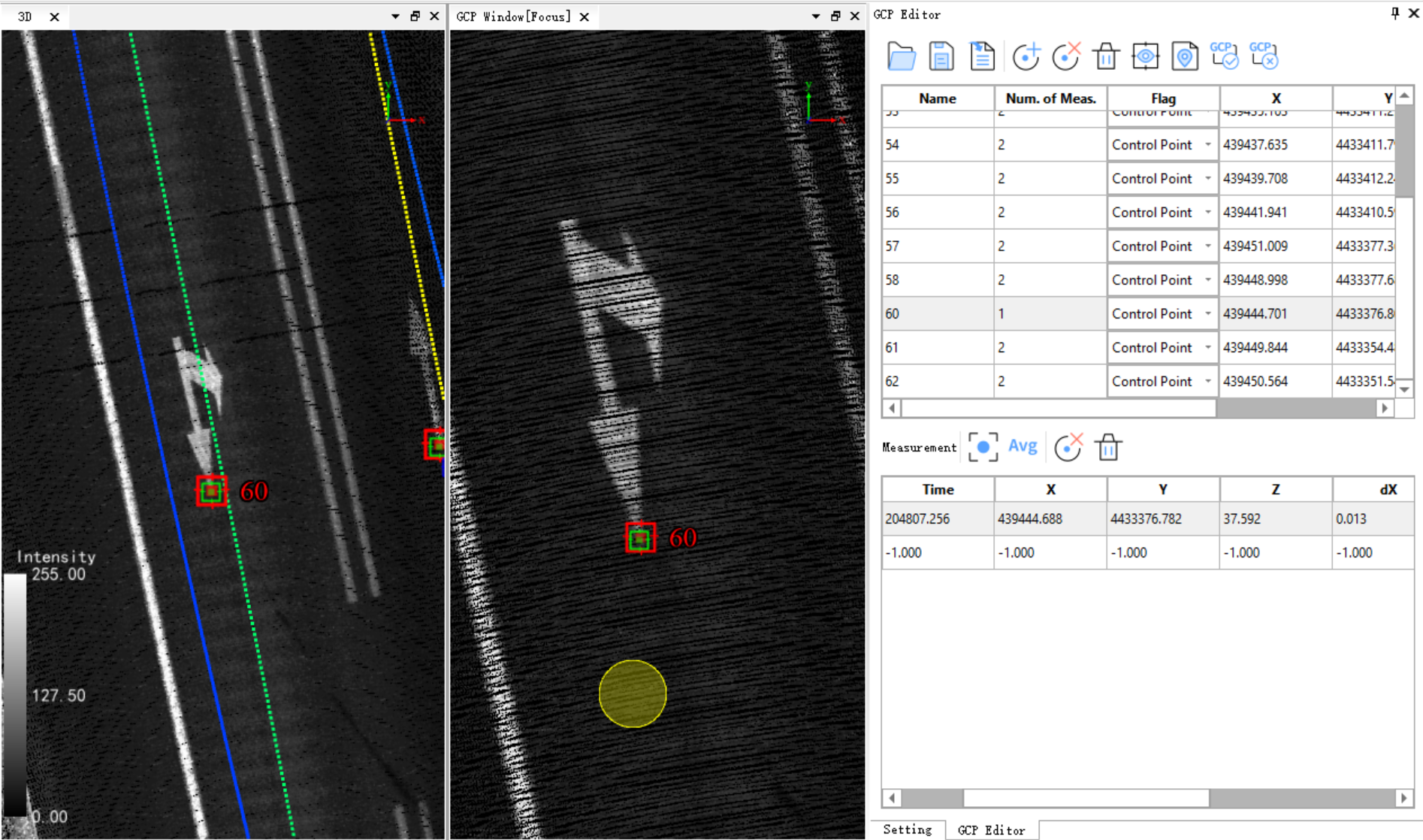
Punctum
6.When all punctums corresponding to all control points are completed, click Report![]() button will pop up the Report dialog box, and users can check the control points based on the punctum information.
button will pop up the Report dialog box, and users can check the control points based on the punctum information.

Report
7.After the correction accuracy is confirmed, close the Report dialog box and click Save![]() button, the GCP control point information will be saved as the PointControl.xlm file and displayed in the directory tree on the left side of the software interface. The user can control whether to display it by checking.
button, the GCP control point information will be saved as the PointControl.xlm file and displayed in the directory tree on the left side of the software interface. The user can control whether to display it by checking.
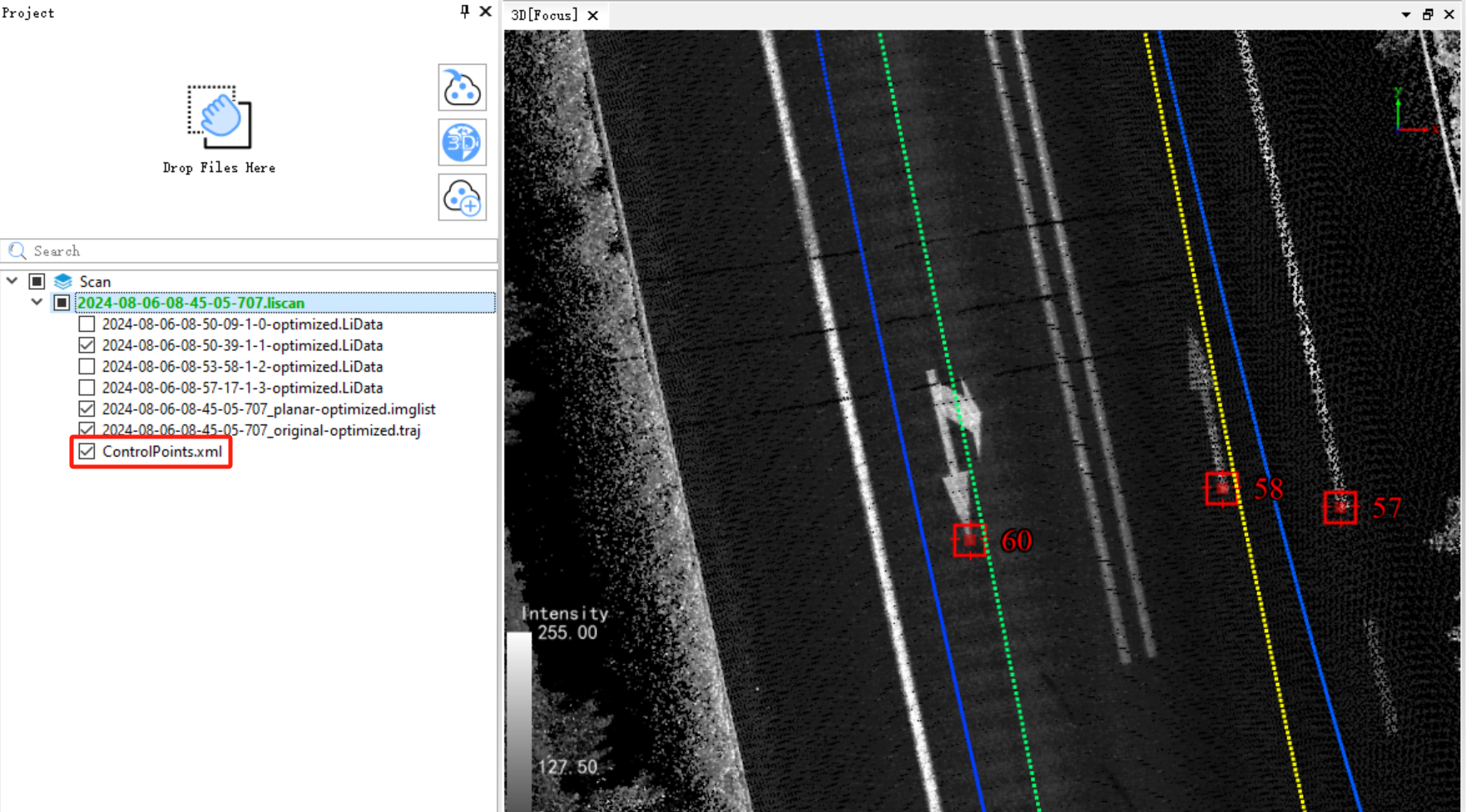
ControlPoint.xlm File Display