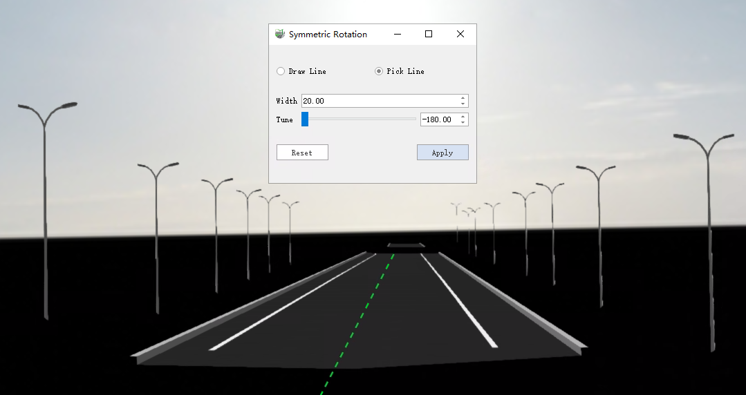
Symmetric Rotation
Some facilities such as street lamps, whose arms should point to the center of the road, are added to the scene in the x-axis direction, and this function can batch adjust such facilities to the correct position.
Steps
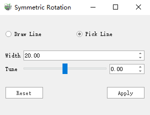
1.Click the function button to bring up the interactive dialog box.
- Draw Line: Draws the range centerline at the center of the road in the direction of Yanshen.
- Pick Line : If a vector such as Lane Centerline already exists, click on the vector and the line segment selected for the vector will be the centerline of the range.
- Width : The length extending from the range centerline to both sides.
- Tune : If the initial orientation of the model may not be X-axis orientation, or the direction of the vector segments is not correct, you can use trimming to adjust to the correct position.
- Reset : Abandon the current modification.
- Apply: Save and apply the changes.
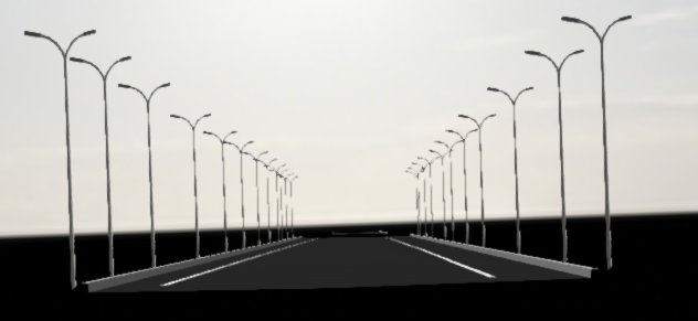
2.Select the road facilities to adjust the layer. As shown in the figure on both sides of the main pick arm of the street lamp are pointing to the left.
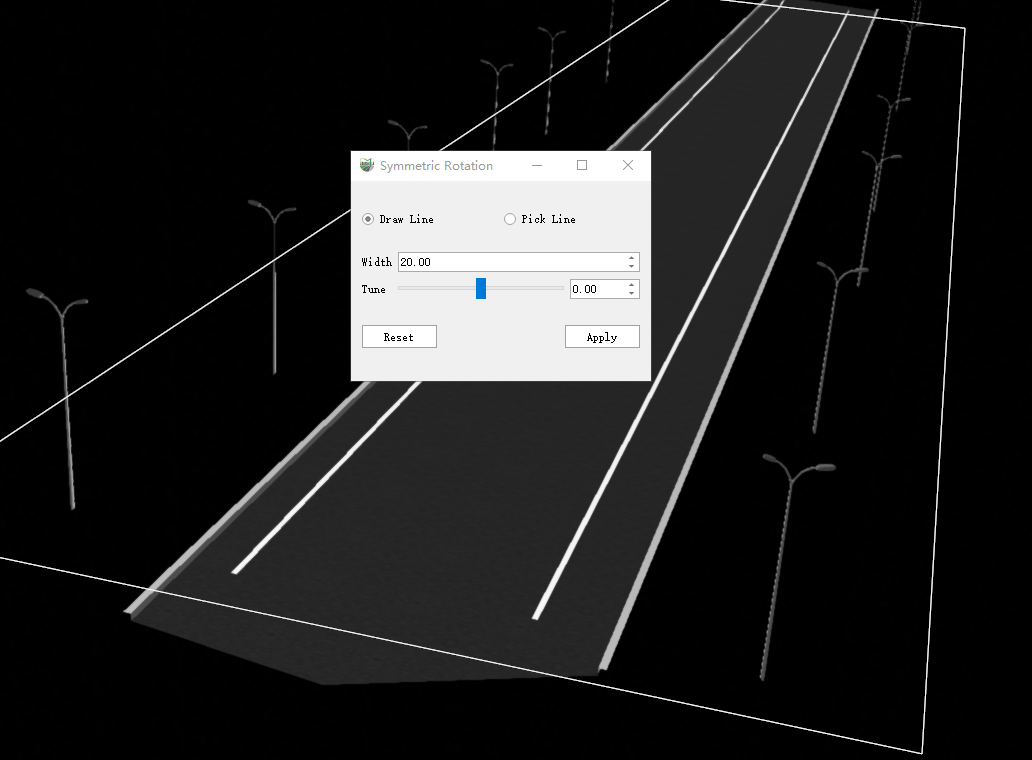
3.Draw a line or pick a road vector line that exists.
- Draw line: Draws an area covering the facility to be rotated. The first click determines the starting point, and the width can be adjusted during drawing, while the second click determines the area and rotates the covered facility.
- Pick Line: Move the mouse pointer to the vector, capture the line vector and display the covered area, click to identify the area and rotate the covered facility.
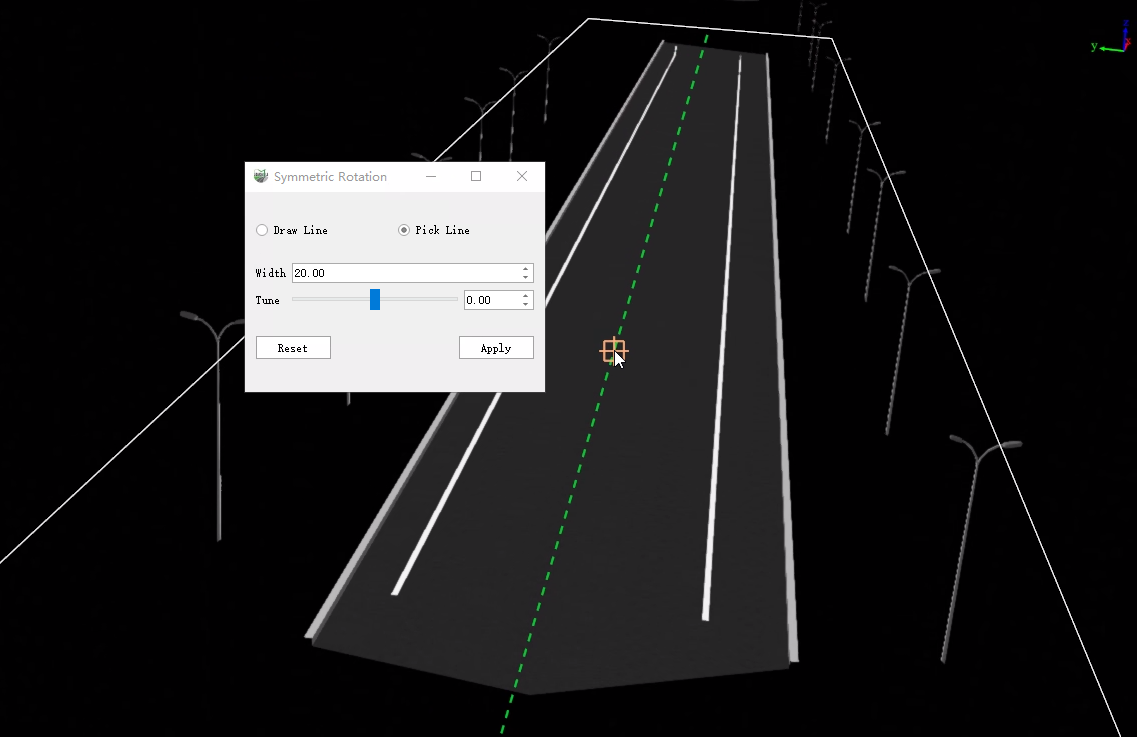
The picket arms of the streetlights on both sides of the picture are pointing outwards
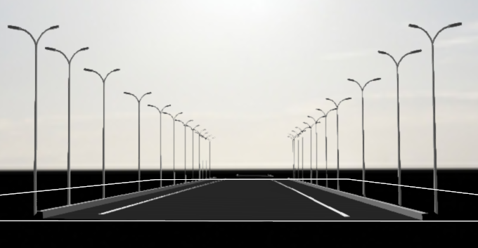
4.Drag the Tune slider to turn the model to the correct position.
