Road Surface Key Points By Grid
Note: It is strongly recommended to perform point cloud classification in advance to get the correct road surface TIN.
Steps
1.Click the Road Surface Key Points By Grid ![]() button.
button.
2.The Road Surface Key Points By Grid Extraction Dialog pops up:

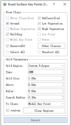
Road Surface Key Points Dialog
Parameter Explanation:
- From Class: Select the point cloud class involved in generating key points. To accurately express the road surface, it is recommended to perform point cloud classification in advance and only select the category where the road surface is located.
Grid Region: Choose the range of the area where you need to generate key points.
- Custom Polygon: Users can manually click on the point cloud according to their needs. Click the left mouse button to add a point, and double-clicking the left mouse button ends, thus forming a polygon.
- Existing Polygon: Click the left mouse button to select an existing polygon as the grid area.
- All Files: This option means to extract key points from all point clouds of the selected source category in the current project, without manually selecting/generating polygon areas.
Type: Indicate the type of key points used to finally construct TIN. The default is DEM.
- DEM: In this mode, the generated key points can be used to generate DEM (Digital Elevation Model).
- DSM: In this mode, the generated key points can be used to generate DSM (Digital Surface Model).
- Grid Size: This function uses a uniform grid to generate key points, and this option represents the size of a single cell. The default is 1.0 meters.
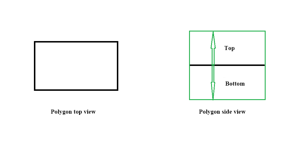
- Above, Below: Used in conjunction with the grid area to capture the three-dimensional area above and below the grid area. See the illustration below for specifics.

Three-dimensional area illustration
- Search Radius: Each grid key point needs to search around the point cloud when it is close to the ground. This parameter is used to determine the radius.
- To Class: The class in which the detected key points are to be saved.
- Contour: If checked, key points are also generated under the polygon contour line. If unchecked, key points only exist at uniform grid points.
- Clear Regions: Clear the custom polygon area.
- Detect: Start the detection function.
3.Grid Area Definition
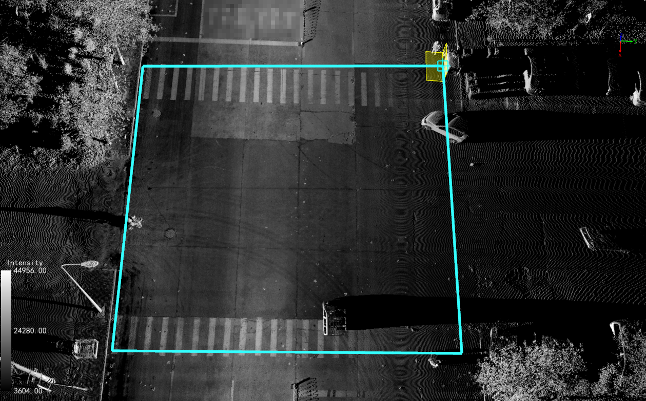
- In the custom polygon mode, the left mouse button is clicked in sequence to select the road surface point cloud, and the mouse is double-clicked to end the polygon production.
Click the left mouse button to add a polygon point; right-click the mouse to go back to one point; double-click the left mouse button to end the drawing.
- In the existing polygon mode, click the left mouse button to select an existing polygon. Multiple selections can be made.
- In the all-files mode, there is no need to define the grid area.

Grid Area
4.Click the Detect button to open the probe and wait for the probe to finish.
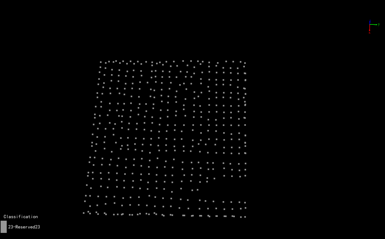
5.Result check: Render the point cloud according to the class information and check whether the key point results are reasonable or have any errors. For any errors, you can use the sorting tool by attributes in the sorting tool (which can perform class reclassification and key point clearing operation), as well as use manual sorting to correct the key points.

Results Show