Buffer
Function Description: Creates buffer polygons around input features within a specified distance.
How it works
The buffer tool traverses each vertex of the input features and creates buffer offsets. These offsets are used to generate the output buffer features.
Buffer Process
1.Input line feature
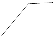
Input line feature
2.Offsets created around the input line feature
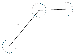
Offsets created
3.Buffer derived from the offsets
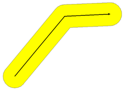
Buffer derived from the offsets
Buffer distance
The buffer distance parameter can be entered as a fixed value or as a field containing numeric values.
1.Fixed distance
The following shows the buffer of a line feature class using a distance of 20, an end type of FLAT, a side type of FULL, and a dissolve type of ALL.
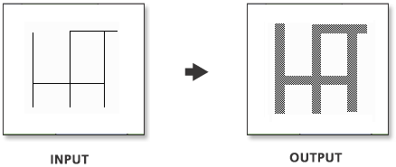
Fixed distance
Because the buffer distance is a constant, all features are buffered to the same width.
2.Distance from field
This example illustrates the buffer of a line feature class using a numeric field with values of 10, 20, and 30 for distance, an end type of FLAT, a side type of FULL, and a dissolve type of ALL.
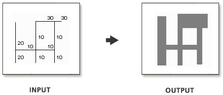
Distance from field
Because the buffer distances are dependent on the field values, various buffer widths can be applied in the same operation.
Data Description
Input and Output Relationship
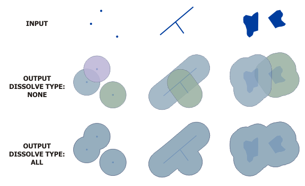
Input and Output Relationship for Buffer
Notes:
If the input is in a projected coordinate system and the output is a geodatabase feature class, the output may contain arc segments. When the input is a point feature class, the output will always be an arc. If arcs are projected to a different coordinate system, the original buffer's location and size will be distorted. However, the shape of the buffer will remain the same, which may result in the projected buffer not accurately representing the area covered by the original buffer.
The output feature class will include a
BUFF_DISTfield, which contains the buffer distance used for each feature (using the linear units of the input coordinate system). If a field namedBUFF_DISTexists in the input, its values will be overwritten in the output. If theMerge Typevalue is set toALLorLIST, this field will not be included in the output.The output feature class will include an
ORIG_FIDfield, which contains the feature ID of the input feature for which the buffer was created. If a field namedORIG_FIDexists in the input, its values will be overwritten in the output. If theMerge Typevalue is set toALLorLIST, this field will not be included in the output.For polygon features, a negative buffer distance can be used to create a buffer inside the polygon. Using a negative buffer distance will shrink the polygon boundary inward by the specified distance.
Note: If the negative buffer distance is large enough to reduce the polygon to a non-existent state, empty geometries will be generated. A warning message will appear, and no empty geometries will be written to the output feature class.
If a field in the input is used to determine the buffer distance, the values in that field can be numeric (e.g., 5) or numeric with valid linear units (e.g., 5 km). If the field value is numeric, the distance is assumed to use the linear units of the input spatial reference (unless the input uses a geographic coordinate system, in which case the value is in meters). If the linear units specified in the field value are invalid or unrecognized, the default is to use the linear units of the input spatial reference.
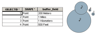
Example of Using a Field to Obtain Buffer Distance
Buffer operations do not support transferring the z-values or m-values of the input data coordinates from the input buffer features to the output buffer features.
Steps
1.Locate the Toolbox -> Vector Tools -> Overlay Analysis -> Buffer tool, and double-click to open the tool window.
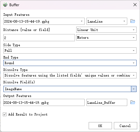
Buffer
Parameter Description:
- Input Features: The input point, line, or polygon features to be buffered.
- Distance [value or field]: The distance from the input features to create the buffer. This distance can be specified as a linear distance value or as a field in the input features that contains the buffer distance for each feature. If no linear unit is specified or "unknown" is entered, the linear unit of the input feature's spatial reference will be used.
- Side Type (Optional): Specifies which side of the input features the buffer will be created on. This parameter is applicable only to polygon and line features.
- Full—For lines, a buffer will be created on both sides of the line. For polygons, a buffer will be created around the polygon, including and overlapping the area of the input features. This is the default setting.
- Left—For lines, a buffer will be created on the topological left side of the line. This option is not applicable to polygon input features.
- Right—For lines, a buffer will be created on the topological right side of the line. This option is not applicable to polygon input features.
- Exclude Input Polygon from Buffer—For polygons, only a buffer will be created outside the input polygon (areas inside the polygon will be erased from the output buffer). This option is not applicable to line input features.
- End Type (Optional): Specifies the shape of the buffer at the ends of line input features. This parameter is not applicable to polygon input features.
- Round—The ends of the buffer are rounded or semi-circular. This is the default setting.
- Flat—The ends of the buffer are flat or square, terminating at the endpoints of the input line feature.
- Square—The ends of the buffer are square, extending a buffer distance beyond the endpoints of the input line feature.
- Dissolve Type (Optional): Specifies the type of merging to remove buffer overlaps.
- No Merge—Overlaps are ignored, and each feature's buffer is maintained independently. This is the default setting.
- Dissolve all output features into a Single feature—All buffers are merged into a single feature, removing all overlaps.
- Dissolve features using the listed fields' unique values or combination of values—Buffers are merged based on shared values from the listed fields (carried from the input features).
- Dissolve Field(s) (Optional): A list of fields from the input features used for merging the output buffers. Buffers sharing listed field values (carried from the input features) will be merged.
- Output Features: The feature class containing the output buffers.
- Add Result to Project: This option is only effective if the output feature class is saved to the GPKG database in the project. Checking this option will automatically create a layer for the result data and add it to the project.