Line to Polygon
Function Description: Create polygons based on the selected vector line or the selected vector line layer.
Principle
The schematic diagram is as follows, the black solid line in the middle is the reference vector line, and the outer dotted box is the generated polygon.
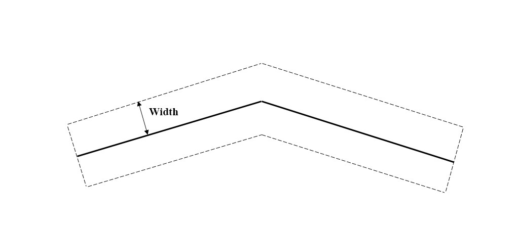
Schematic Diagram
Steps
1.Click the Line to Polygon![]() button in the Vector Editor.
button in the Vector Editor.
2.The Line to Polygon Dialog Box pops up.
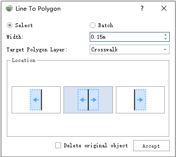
Select
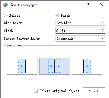
Batch Process
Parameter Description:
- Select: Single click on a vector line with the left mouse button to generate a polygon.
- Batch: Generate polygons for all vector line objects within the line layer.
- Line Layer: Only appears in batch processing mode, used to select the source layer of the vector line.
- Width: The width of the polygon.
- Target Polygon Layer: The layer in which the generated polygon will be stored.
Location: Used to specify which side of the reference line the generated polygon is located on, default is middle.
- Left: Generate the set width polygon on the left of the baseline.
- Middle: Generate the set width polygon on both sides of the baseline, the left width is half of the width, and the right width is half of the width.
- Right: Generate the set width polygon on the right of the baseline.
Delete original object: Whether to delete the baseline, or default is not checked.
- Accept/Start: In point mode, the polygon style will be displayed in real time, and the polygon will be generated after clicking the accept button; in batch processing mode, there is no real-time display, clicking the start button will start to generate polygons in batches.
Solid Line Result
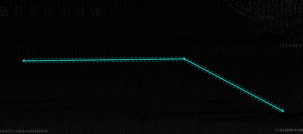
Solid Line Result
Dashed Line Result
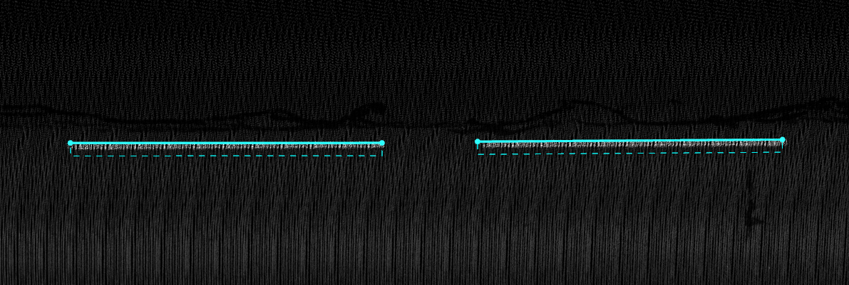
Dashed Line Result