Add Line
Function Description: This tool allows the user to add vector lines to objects.
Steps
1.Select a linear layer, such as a lane line layer.
2.Click Add Line ![]() button in the Vector Editor. Use the mouse to select the starting point of the line in the point cloud, click the left mouse button continuously to confirm multiple nodes of the line, and double-click the left mouse button to end the drawing of the current line.
button in the Vector Editor. Use the mouse to select the starting point of the line in the point cloud, click the left mouse button continuously to confirm multiple nodes of the line, and double-click the left mouse button to end the drawing of the current line.
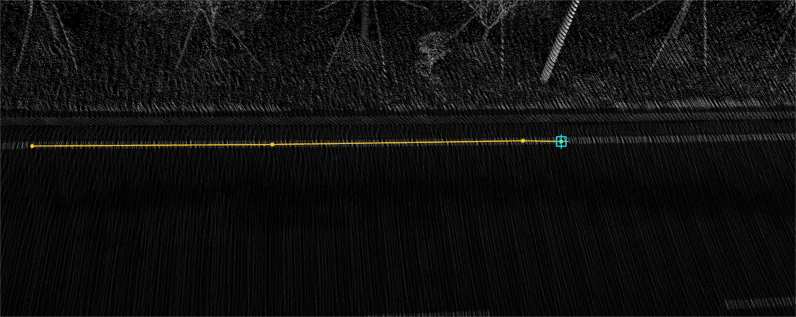
Draw line interface
3.During the drawing process, you can use different shortcut keys to switch between different modes:
| Function | Shortcut | Description |
|---|---|---|
| Drawing Arc | S/s | Short press the s key to switch the drawing mode from drawing a straight line to drawing an arc. The arc adopts the three-point mode. The first point is the last point before short press s, the second point is the end point of the arc, and the third point controls the arc |
| Backing off a point | B/b | Press b briefly to back out of the drawn node |
| Tracking Mode | T/t | In the area where vector tracking needs to be activated, press the "T" key briefly to switch to tracking mode. Once in tracking mode, click on a starting point on the object to be tracked. While moving the mouse along the object to be tracked, vector nodes will be automatically collected without the need for manual node placement. During the tracking process, you can cancel the current tracking by right-clicking the mouse. Note that after cancellation, not only will the tracked nodes be cleared, but the tracking mode will also be exited by default. If you only want to cancel part of the tracking, you can reverse the mouse movement while tracking to undo the tracked nodes. When you need to stop tracking, simply click the left mouse button once at the ending position, and it will automatically switch back to normal drawing mode. |
| Plot Spline Curve | F/f | During the drawing process, if you need to create a Spline curve, you can press the "F" key to switch to Spline curve drawing mode. In this mode, the added nodes will be calculated and added according to the Spline curve. |
| Drawing Bezier Curves | G/g | During the drawing process, if you need to create a Bézier curve, you can press the "G" key to switch to Bézier curve drawing mode. In this mode, the added nodes will be calculated and added according to the Bézier curve. |
4.During the drawing process, right-clicking the mouse can include the following operations:
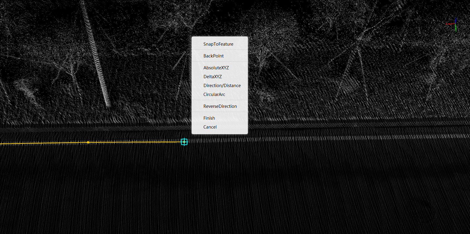
- SnapToFeature: You can switch various capture modes at any time in the SnapToFeature menu.
- BackPoint: Click BackPoint to fallback nodes in order. (the first node cannot be rolled back). During drawing, the shortcut key of BackPoint is b/B.
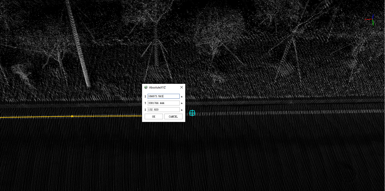
- AbsoluteXYZ: With the AbsoluteXYZ function, you can specify the coordinates of AbsoluteXYZ during the drawing process. The coordinate value entered in the pop-up box is the position drawn by the node.
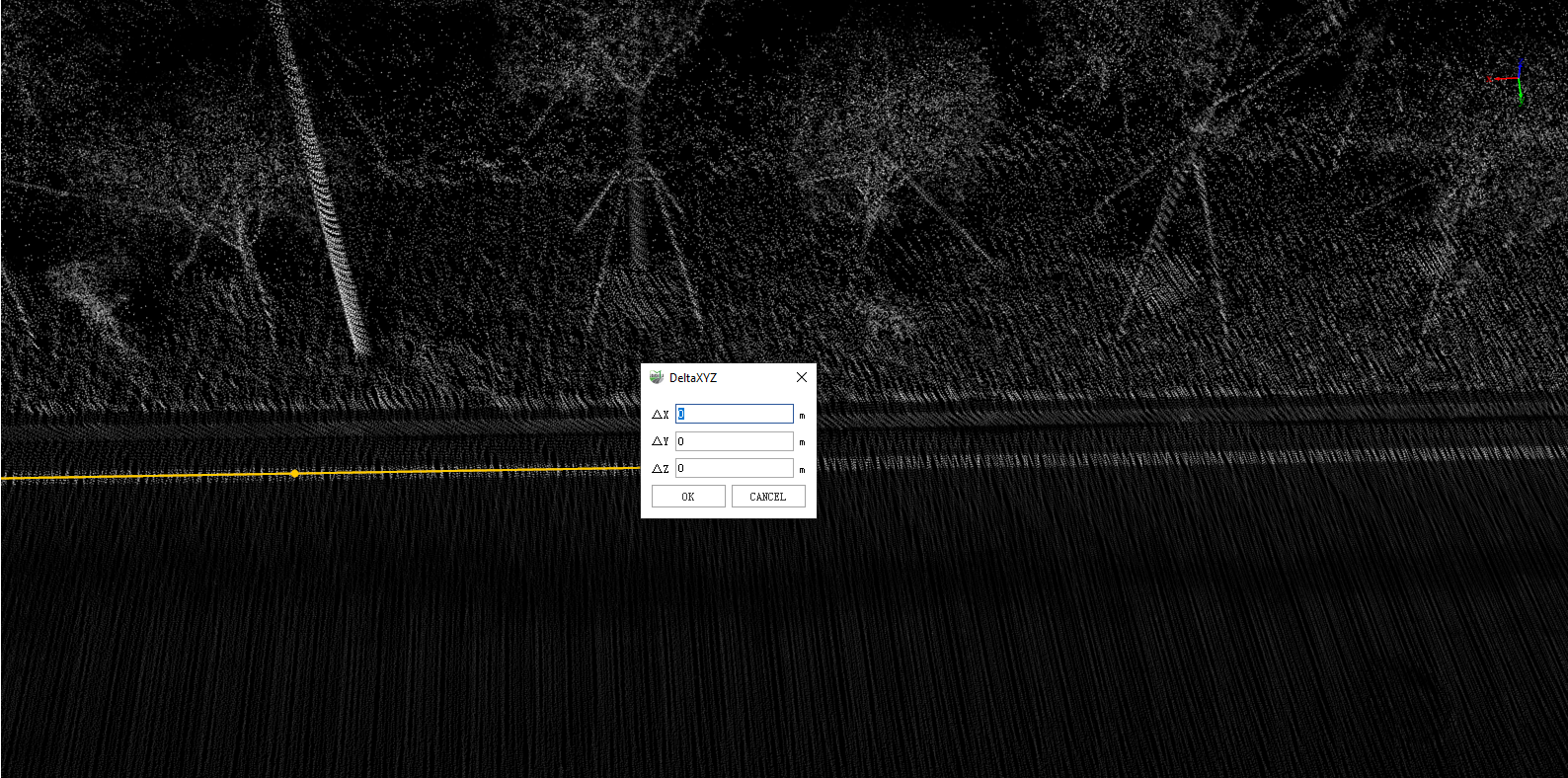
- DeltaXYZ: With the DeltaXYZ function, you can specify the coordinate position of the next node relative to the previous node in the drawing process. The coordinate value entered in the pop-up box is the position relationship between the next node and the previous node.
- Direction/Distance: With the Direction/Distance function, you can specify the direction and distance of the next node relative to the previous node in the drawing process. The yaw angle is the included angle with the Y axis of the coordinate system, the pitch angle is the included angle with the XY plane of the coordinate system, and the distance is the distance between the next point and the next point in the above angular direction. In the profile window, there is no need to modify the yaw angle.
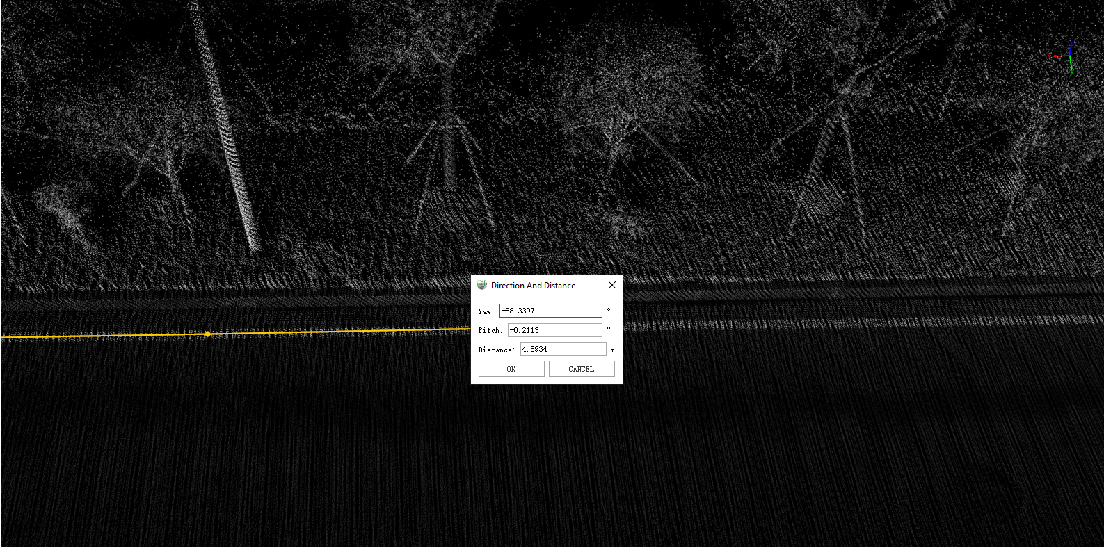
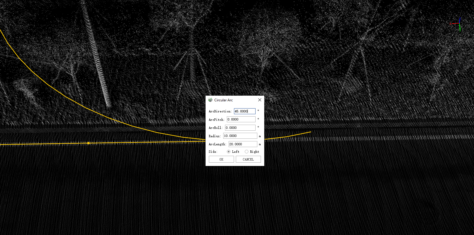
- Circular Arc: With the circular arc function, an arc with a specified direction, size and position can be generated during the drawing process. As shown in the following figure, the ArcDirection refers to the angle of the arc relative to the Y axis of the coordinate system, ArcPitch refers to the direction relative to the XY plane of the coordinate axis, and ArcRoll refers to the rotation angle around the XY plane of the coordinate axis. Radius refers to the length of the two ends of the generated arc, ArcLength refers to the side length of the generated arc, and Side controls the current plane position to the left or right. (Note: the profile window is not applicable to arc calculation, and the generated arc will not be displayed completely in the profile window)
- ReverseDirection: During the line drawing process, the direction of the drawn vector line can be reversed with the ReverseDirection function, and the drawing can continue based on the new direction.
- Finish: During the drawing process, you can double-click the last node with the left mouse button to complete the drawing, or you can click the Finish button in the pop-up box with the right mouse button to end the drawing of the current object.
- Cancel: During the drawing process, you can click the right mouse button to pop up the Cancel button to exit the current drawing.
Note:
- The geometric characteristics of the vector result must be consistent with the geometric characteristics of the layer to be added. For example, the point-like vector result must be added to the point-like layer, otherwise it will be prompted that it cannot be drawn. For the description of layers, see Layer Management.