Road Design cross section Data Preparation
Design longitudinal Axis Creation
Function Description: Create a design longitudinal axis.
Creation
Function Description: Left-click with the mouse to manually create a design longitudinal axis.
Steps
1.Click sequentially with the left mouse button. 2.Double-click the left mouse button to finish the creation.

Longitudinal Section
Selection
Function Description: Left-click with the mouse to select an existing line object as the design vertical axis.
Design Cross Section Creation
Function Description: Automatically or manually create a design cross Section.
Automatic
Function Description: Automatically generate reference cross sections based on the set parameters.
Parameter Dialog
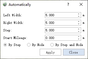
Dialog
Parameter Description
- Left Width: The distance from the leftmost point of the cross section reference line to the vertical reference line, defaulting to "5". If using road attributes for calculation, it should be set to half the lane width.
- Right Width: The distance from the rightmost point of the cross section reference line to the vertical reference line, defaulting to "5". If using road attributes for calculation, it should be set to half the lane width.
- Step: The step length for generating reference cross sections.
- Start Mileage (default is "0"): The starting mileage for generating reference cross sections; the mileage for each cross section will accumulate based on this. The starting mileage stakes for different sections of the road may vary, and cross sections are named by default in the form of stake km + m. Users can modify the names of the cross sections as needed.
- By Step: Generate reference cross sections at specific step lengths.
- By Node: Generate reference cross sections only at nodes, where nodes refer to the nodes of the vertical reference line itself.
- By Step and Node: Generate reference cross sections at specific step lengths while also processing the nodes.
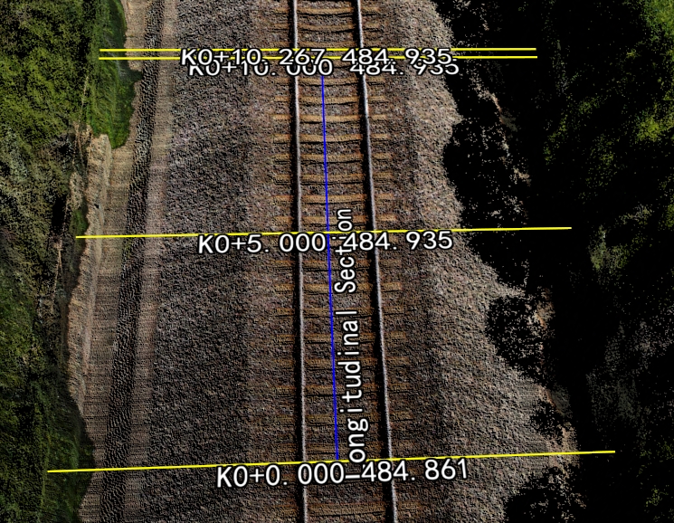
Effect Diagram
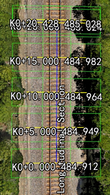
The blue vector line represents the manually drawn design vertical axis, while the yellow line represents the automatically generated cross section reference line according to the specified step length.
Manual
Function Description: Based on the set parameters, use the left mouse button to click at the location on the design vertical axis where a design cross-section needs to be added, generating a reference cross-section.
Parameter Dialog
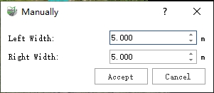
Parameter Dialog
Parameter Description
- Left Width: Default is 5.0 meters; this is the distance from the leftmost point of the design cross section line to the design longitudinal axis.
- Right Width: Default is 5.0 meters; this is the distance from the rightmost point of the design cross section line to the design longitudinal axis.
- Accept/Cancel: Accept or cancel the manual results.
Steps
Move the mouse to any centerline and click the left mouse button to add a new design cross section to the design longitudinal axis.
Extract Point Cloud Along Cross Section
Function Description: Perform point cloud slicing along the design longitudinal section or design cross section.
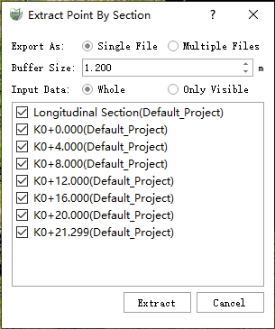
Parameter Dialog
Parameter Description
- Export As:
- Single File: The sliced point cloud will be stored as one LiData file.
- Multiple Files: The point clouds sliced from each axis will be independently stored as separate LiData files.
- Buffer Zone: The cutting range in the horizontal direction (based on each axis).
- Input Data:
- All: Use all point clouds.
- Only Visible: Only use the currently displayed point clouds for slicing calculations.
Steps
1.Adjust parameters.
Parameter Dialog
2.Run.