Data Management
Design Data
Description: Consists of two parts: the design longitudinal axis and the design cross axis. The design longitudinal axis can be manually created with the Create ![]() button, or an existing vector line can be selected as the design longitudinal axis using the Select
button, or an existing vector line can be selected as the design longitudinal axis using the Select ![]() button. The design cross axis can be automatically generated using the Auto
button. The design cross axis can be automatically generated using the Auto ![]() button based on set step length and width, or it can be generated at the mouse click location using the Manual
button based on set step length and width, or it can be generated at the mouse click location using the Manual ![]() button.
button.
Principles:
1.Each analysis project must have only one set of design data, and all measurement data groups within the project share this design data.
2.Updates, deletions, or additions to the design data will affect all measurement data groups in the current project.
3.Generally, design data does not need to conform to the ground surface.
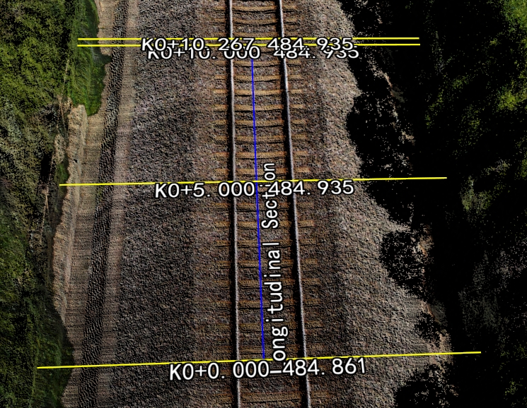
Design Data 1

Design Data 2
Measurement Data
Description: Measurement data is generated based on design data and corresponding point cloud data, represented as 3D and 2D vector lines that fit the ground surface.
Principles:
1.The measurement data completely coincides with the design data in the X and Y coordinates, appearing identical from a top-down view.
2.The names of the longitudinal and transverse axes for all measurement data groups in the current project must match those of the design data.
3.Measurement data must fit the ground surface (consistent with the point cloud used for calculations).
4.Different point clouds from different periods can generate distinct measurement data.
5.Changes between different measurement data groups can be compared.
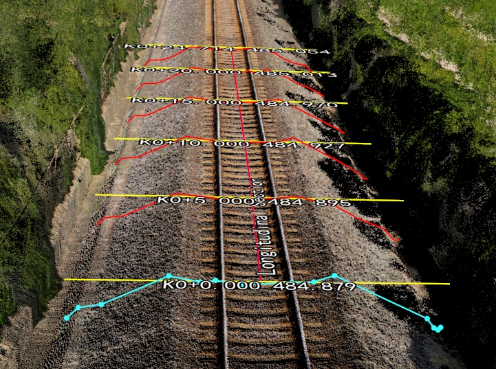
Schematic diagram of the measurement data
Analysis Project
Description: An analysis project consists of a group of design data and its corresponding series of measurement data groups. Specific operations can be viewed through the directory tree.
Principles:
1.An analysis project is the smallest unit for performing geometric calculations, attribute calculations, and cross-sectional comparisons. Each analysis project must have only one set of design data, which is shared by all measurement data groups within that project.
2.Multiple analysis projects can be stored within a single .section data management file.
3.The design data for different analysis projects are distinct.
4.Only one current active project can be used for calculations at any given time.
Cross-section Names
Description: Naming each cross-section according to the set file.
- Longitudinal Axis: The names for both the design longitudinal axis and the measured longitudinal axis are identical, both referred to as "Longitudinal Section," and customization is not supported.
- Cross Axis: The names for the design cross section and the measured cross section are the same, consisting of a prefix and suffix. Specific details can be found in the directory tree operations section regarding cross-section name settings.
The directory tree only displays the cross-section names; the 3D window shows the elevation of each transverse section along with the cross-section names.
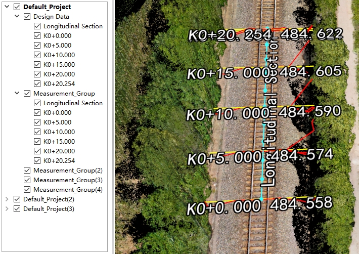
Directory tree
Directory Tree Operations
Description: A visual management tool for section analysis management files, such as the analysis project directory tree displayed below.
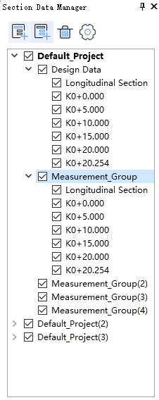
Directory tree
Functionality:
1.Create New Project: Click the New Project ![]() button to add a new empty default project.
button to add a new empty default project.
2.Add Measurement Group: Click the New Measurement Group ![]() button to add an empty measurement data group within the current active project.
button to add an empty measurement data group within the current active project.
3.Delete Selected Item: Left-click on the item in the directory tree, then click the Delete Selected Item ![]() button to delete the selected item. Different selection options correspond to different deletion actions, as illustrated below.
button to delete the selected item. Different selection options correspond to different deletion actions, as illustrated below.
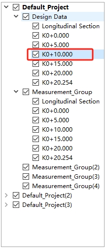
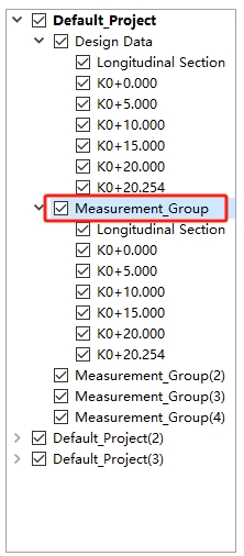
Delete the selected item
Note: Deletion operations cannot be undone. Please use with caution according to the prompts.
4.Section Name Setting: Click the Section Name Setting ![]() button to open the cross-section name settings dialog, where you can customize the names of the cross-sections.
button to open the cross-section name settings dialog, where you can customize the names of the cross-sections.
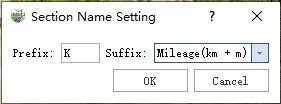
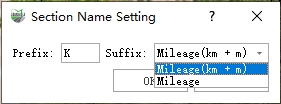
Section Name Setting
Parameters:
- Prefix: The prefix for the cross-section name that can be customized. The default value is "K".
- Suffix: Uses mileage as the suffix for the cross-section name, with different calculation methods available. It includes:
- Mileage (km + m): This option is used only when the point cloud unit is in meters.

Mileage(km + m)
In this context, "K" serves as the prefix. For example, "K0 + 20.00" represents a mileage of 0 km + 20 m, indicating a cross-section at 20 m. The value "485.013" denotes the elevation of the current transverse section (derived from the intersection point between the current transverse section and the longitudinal axis).
- Mileage: This is applicable to data in any unit of measurement.

Mileage
In this context, "K" is the prefix. The cross-section at a mileage of 20 m has an elevation of 485.013, which is derived from the intersection point between the current transverse section and the longitudinal axis.
5.Vector Line Visibility: Click the check box next to each item in the directory to control the visibility of the vector lines.
6.Right-click Menu
1)Right-click on the project item to access additional options and functionalities.
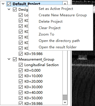
Right-click Menu
- Set as Active Project: Set the selected project as the Active Project. All geometric calculations, attribute calculations, cross-sectional comparisons, and other analytical tools depend on the active project. At any given time, there can be only one active project.
- Create New Measurement Group: Add a new empty measurement data group.
- Delete Project: Delete the selected project. Note that if there is only one analysis project in the current data, it cannot be deleted.
- Clear Project: Clear the selected project, including design data and all measurement data groups. Please use this option with caution.
- Zoom To: Zoom the 3D window to the location of the current project.
- Open the directory path: Open the location of the project file.
- Open the result folder: Open the location of the result file.
2)Right-click Menu for Design Data Groups
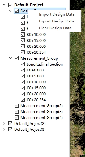
Right-click Menu
Import Design Data: Import existing design data that can be correctly read only if it was exported using the "Export Design Data" function. This feature supports three formats: DXF, SHP, and custom text. It should be used in conjunction with the "Export Design Data" option.
Export Design Data: Export the selected design data group. This function supports DXF, SHP, and custom text formats, facilitating integration with the "Import Design Data" functionality.
Clear Design Data: This action will clear the design data within the selected group, similar to the effect of clearing the entire project. Please use this option with caution, as it is not reversible.
3) Right-click Menu for Design Section
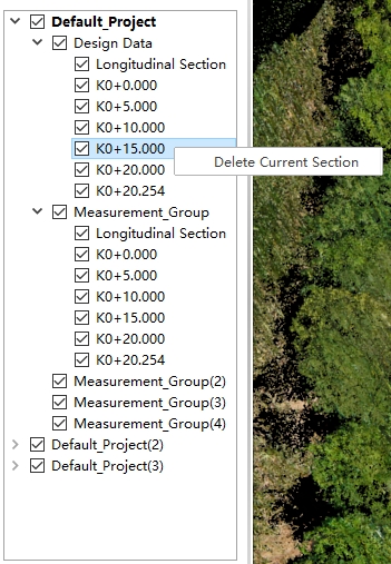
Right-click Menu
- Delete Current Cross-section: Remove the design vertical axis. This action has the same effect as clearing the entire project, so please use it with caution. Deleting the design horizontal axis will also result in the removal of all corresponding measurement cross-sections, so proceed carefully when using this option.
4)Right-click Menu for Measurement Group
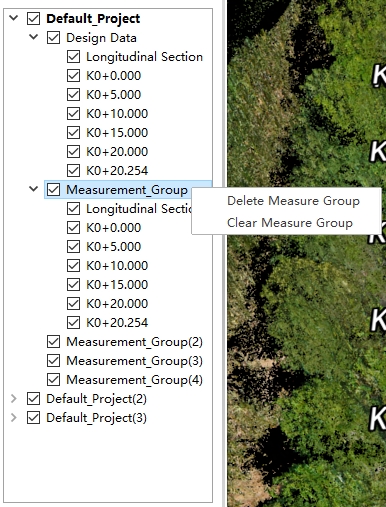
Right-click Menu
- Delete Measurement Group: Remove the currently selected measurement data group from the directory tree.
- Clear Measurement Group: This action will only clear the current measurement data group.