XY Table To Line
Function Description: Creates a feature class containing geodetic and planar line features based on the start point X coordinate field, start point Y coordinate field, end point X coordinate field, and end point Y coordinate field from a table.
Data Description

Example Data
The output lines are constructed based on field values, which include:
- Start point X and Y coordinates
- End point X and Y coordinates
Note: These fields and their values will be included in the output.
For geodetic lines, the X and Y coordinates represent positions on the Earth's surface. For planar lines, the coordinates are positions on the projected plane.
Geodetic lines are curves on the Earth's surface. However, in the output, geodetic line features are not stored as true curves but as densified polylines representing the geodetic path. If the geodetic line is relatively short, it may be represented by straight lines in the output. As the length of the line increases, more vertices are used to represent the path.
Steps
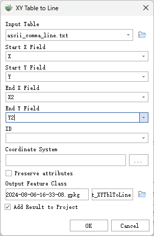
Find the XY Table To Line tool under the toolbox, and double-click to open the tool window.

XY Table To Line
Parameter Description:
- Input Table: The input table. This can be a text file, CSV file, or feature class.
- Start X Field: The numeric field in the input table that contains the start point X coordinate (or longitude) of the line, located in the coordinate system specified by the Spatial Reference parameter.
- Start Y Field: The numeric field in the input table that contains the start point Y coordinate (or latitude) of the line, located in the coordinate system specified by the Spatial Reference parameter.
- End X Field: The numeric field in the input table that contains the end point X coordinate (or longitude) of the line, located in the coordinate system specified by the Spatial Reference parameter.
- End Y Field: The numeric field in the input table that contains the end point Y coordinate (or latitude) of the line, located in the coordinate system specified by the Spatial Reference parameter.
- ID (Optional): A field in the input table. This field and its values will be included in the output and can be used to link output features with records in the input table.
- Coordinate System (Optional): The spatial reference for the output feature class.
Preserve attributes (Optional): Specify whether to include additional input fields in the output feature class.
- Unchecked - The remaining input fields are not added to the output feature class. This is the default setting.
- Checked - The remaining input fields are added to the output feature class. A new field, ORIG_FID, will also be added to store the input feature ID values.
Output Feature Class: The output feature class containing the geodetic and planar lines.
- Add Result to Project: This option is only valid when the output feature class is saved to a geodatabase in the project. If checked, the result data will automatically be added to the project as a layer.