New Liscan Project by Calibration File
Step
1.Click button![]() in the upper left corner of the software main interface. This will open the New Project Wizard dialog.
in the upper left corner of the software main interface. This will open the New Project Wizard dialog.
New Project Wizard
2.File Configuration
2.1 Configure Laser Raw Data
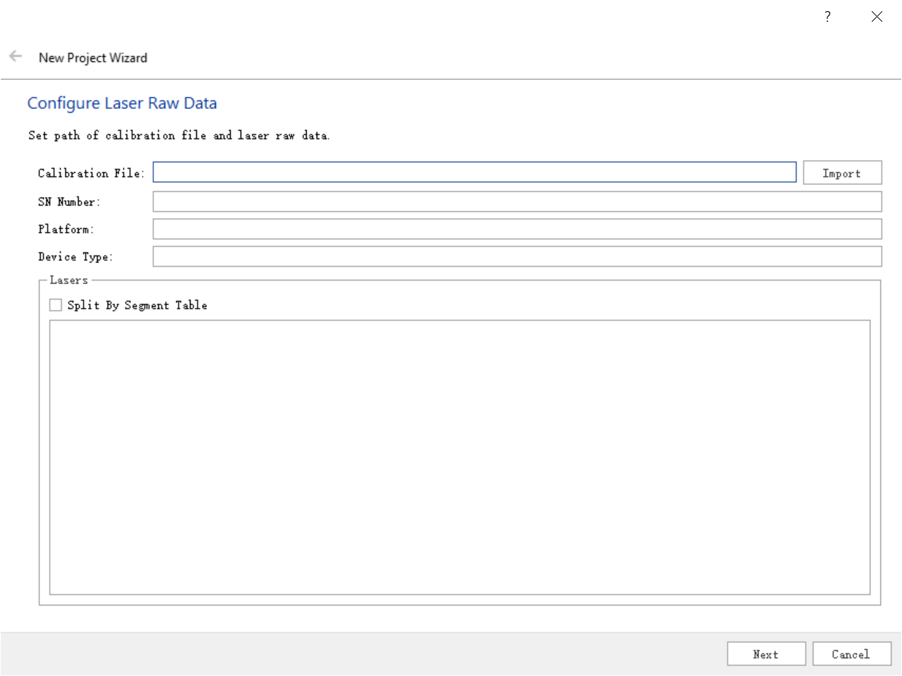
Configure Laser Raw Data
Step
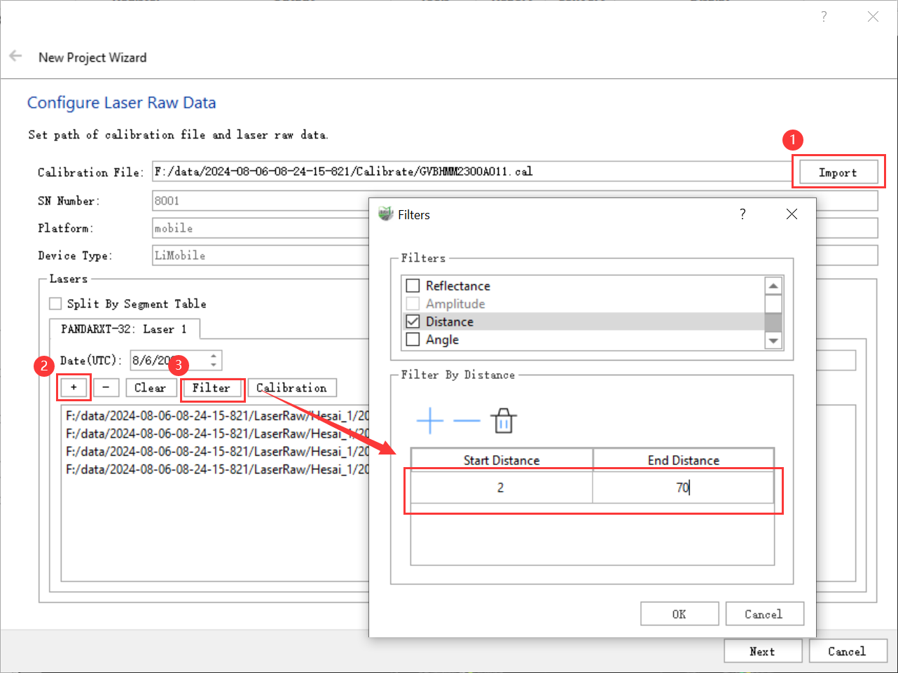
1.Click the Calibration File Import button shown in the figure below to import the *.cal file.
The calibration file of LiMobile M1 is stored in the Calibrate folder under the original data project directory. The calibration file of LiMobile M2 is stored in the Para folder under the original data project directory.Without the calibration file, a new project cannot be created. After importing the calibration file, the software will automatically identify the device SN number, platform, device model and other information.
2.Click the + button to add the original point cloud file.
New projects cannot be created without original point cloud data.
3.Click the Filter button to pop up the Filter interface, check the Filter option, and click the corresponding text to set the filter parameters.
LiMobile M1 requires distance filtering. It is recommended that the starting distance be set to 2 and the ending distance be set to 70.
4.Click the Next button.
Parameter Description
- Calibration File: For each device produced by GreenValley International, there's a calibration fie in *.cal format bounding to it.For customized device, users need to contact our technique supporter to generate configuration file.
- SN: The system serial number of the device. The SN number is exclusive for each device.
- Platform:The vehicle platform is displayed as mobile.
- Device Type: device model, such as LiMobile, etc.
- Date(UTC): The date of data collection.
- Time Offset: The timestamp offset between raw point cloud data and POS data.(The point cloud data and POS processed by LiGeoreference are both UTC time, so the difference will be zero. However, if POS file is imported externally, there might be difference. For example, if the POS file imported is recorded by atomic time, leap seconds need to be added as the offset.
- +: Add point cloud data.
- -: Delete point cloud data.
- Clear: Clear point cloud data.
- Filter:There are several filter options for point cloud data processing
- Reflectance:Filter by reflectance.
- Distance: Filter by distance, where distance refers to the distance between point cloud and laser scanner center.
- Angle: Filer by angle, where angle refers to the angle between point cloud to laser scanner center, 0 degree at forward direction and increase clockwise.
- Laser Line: Filter by laser line. Only save the point cloud data when its line id is checked.
- Thinning: There are two methods of thinning, the interval sampling and grid sampling. If you select interval sampling, the point cloud will be thinned every point according to the set multiple.
- Split by Number of Points: If the number of points in a single original point cloud exceeds the maximum number of points, the file will be split by the set number of points during solution.
- Split by Time Interval: Split the point cloud by time interval. If the time span in a single original point cloud exceeds the maximum time interval, the file will be split at the set time interval during solution.
- Calibration: The calibration parameters of laser scanner center to carrier center, imported by calibration file,users can also edit.Delta Roll, Pitch, Yaw represents the amount of angular rotation, and Delta X, Y, Z represents the amount of coordinate translation.
2.2 Configure POS Raw Data
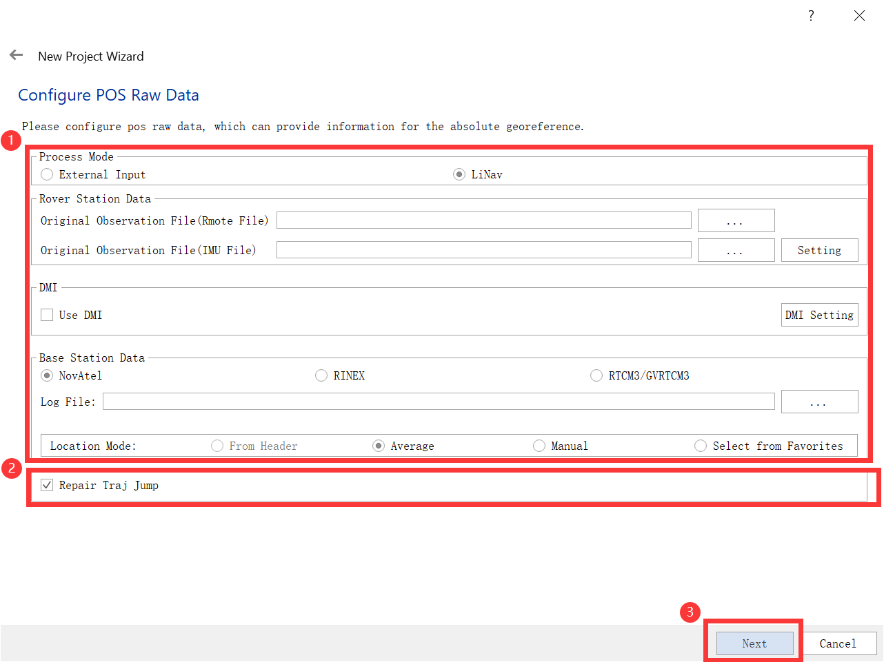
Configure POS Raw Data
Step
1.Select the data processing mode and configure relevant parameters.
2.Repair Traj Jump settings.
3.Click the Next button.
Parameter Description
Process Mode_Linav: Post-process POS file by LiNav module. Click LiNav and turn to LiNav page, set base station and rover station data. The result POS file is in *.pos format.
- Rover Station File: GNSS data obtained by field collection equipment.
- IMU File: INS data acquired by field acquisition equipment.
- DMI: If the user has collected DMI data, check DMI, and then click the DMI Setting button to pop up the DMI Option dialog box. The user needs to measure the lever arm position and wheel circumference by themselves. And fill in the measurement data accurately. For specific measurement methods, see DMI Installation Instructions.
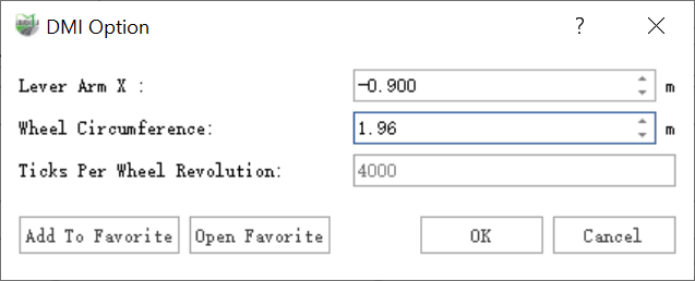
DMI Option
- Base Station Data:The base station data has four modes: NovAtel, RINEX, and RTCM3/GVRTCM3.
- Location Mode: Calculation mode of base station coordinates.
- From Header: Read from header. The default selection when the base station is Rinex.
- Manual: Manual input mode, input WGS84 longitude and latitude coordinates (optional degree minute second format or degree format), ball height and antenna. When setting the latitude and longitude, when the actual latitude is positive, north should be selected, otherwise south should be selected. If the actual longitude is positive, choose east, otherwise choose west. Fill in the longitude and latitude values as positive numbers. After manually adding the base station coordinates, click the Save to Favorites button. In the pop-up Favorites dialog box, the user needs to enter the name. After clicking the Confirm button, the parameters will be Record in favorites.At the same time, the software also supports custom selection of coordinate system, and the conversion can be performed by entering X, Y, Z and antenna height.
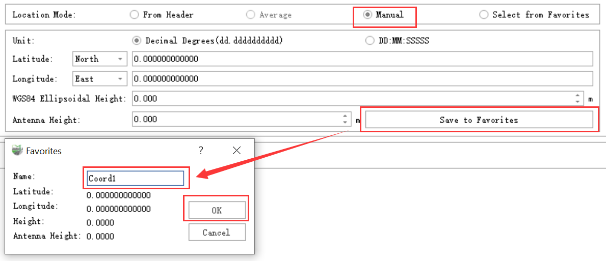
Location Mode-Manual(WGS84)

Location Mode-Manual(Custom)
- Select from Favorites: Select base station coordinate parameters from the favorites list. Click the Select from Favorites button, and you can view the coordinate list in the pop-up Favorites dialog box. Select the required coordinates and click the OK button. If you need to delete the entry, select it and click Just click the Delete button. When used for the first time, the list is empty and needs to be entered in manual mode and click Save to Favorites to save.
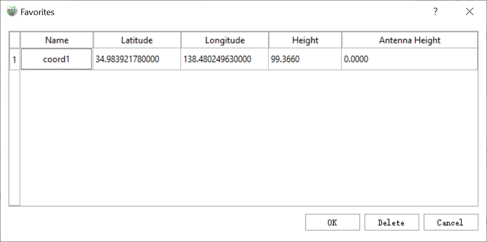
Favorite
Process Mode_External Input: Import existing trajectory files. Click the External Input button to switch the page to external input mode. Click to select the corresponding file, and the Open ASCII File dialog box will pop up.

Process Mode_Externel Input
- Repair Traj Jump: Used to detect and repair trajectory segments with horizontal/elevation jumps in the trajectory. If it is not checked, the software will detect the jump segments in the POS Process step; if it is checked, after the software detects the jump segments, it will repair the segment accordingly.
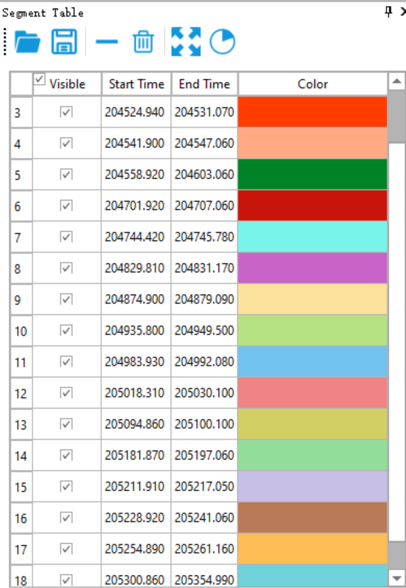
Users can click Segment Table on the trajectory menu bar to view jump segments.
Segment Table
2.3 Configure Camera Raw Data
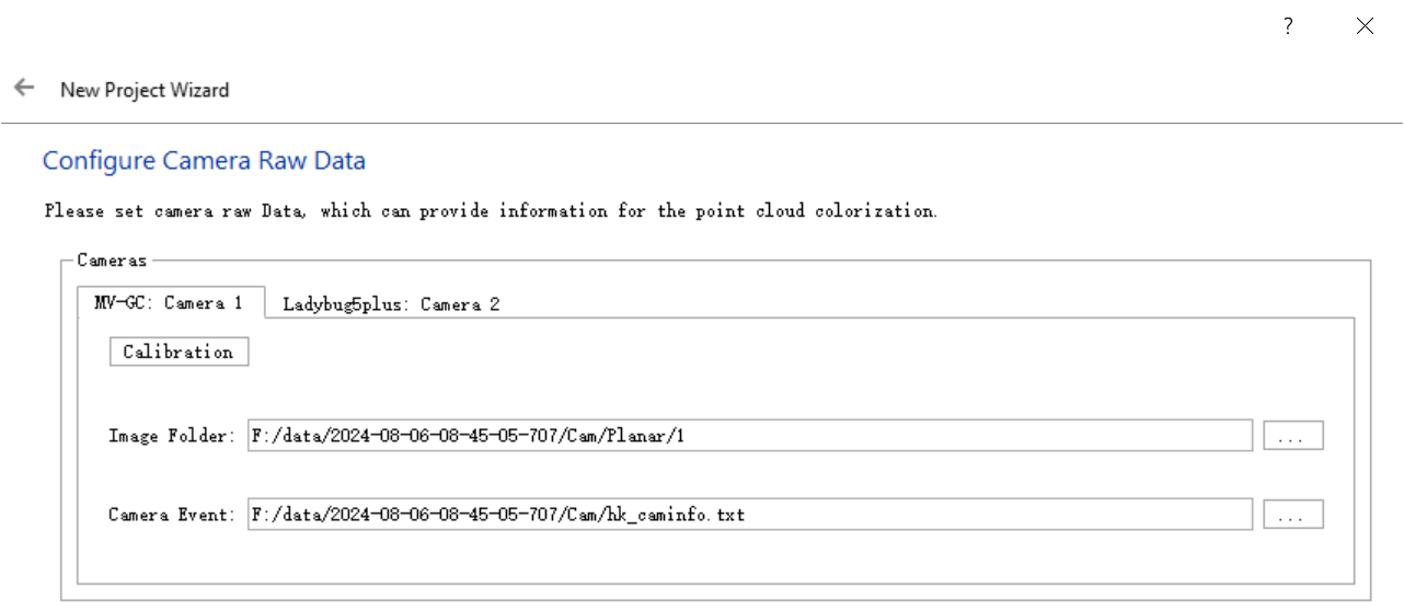
Configure Planar Camera Raw Data
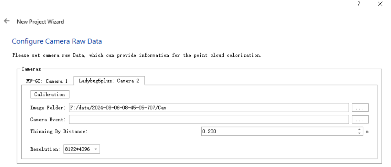
Configure Panorama Camera Raw Data
Step
1.Configure the camera 1 and add the image folder path and camera Event respectively.
2.Switch the tab bar to Camera 2 , add only the image folder path, and leave the camera file empty. Set the thinning distance and resolution.
LiMobile M1 equipment needs to use the default 8192*4096 resolution for processing.
3.Click the Next button.
Parameter Description
- MV-CC_Camera 1:
- Calibration: The calilbration data for camera, imported by calibration file, users can edit.lmage folder.DeltaX, Y, Z represent the coordinate translation amount, Delta Roll, Pitch, Heading represent the angular rotation amount.
- Image Folder: *.jpg format plane image original data directory location.
- Camera Event: Folder where camera file(* txt) stored. Camera file records exposure position and attitue.
- Ladybug5plus_Camera 2:
- Calibration: The calilbration data for camera, imported by calibration file, users can edit.lmage folder.DeltaX, Y, Z represent the coordinate translation amount, Delta Roll, Pitch, Heading represent the angular rotation amount.
- Image Folder: *.pgr format panoramic image source data directory.
- Camera Event: hk_caminfo.txt camera file path. The camera file contains the position and attitude information of the camera at the time of exposure. It is empty before analyzing Panorama.
- Thinning By Distance: thin out the analyzed photos according to the distance interval taken by the camera.
- Resolution: The software supports three resolutions: 8192*4096, 4096*2048, and 2048*1024.
2.4 Configure Target Coordinate System
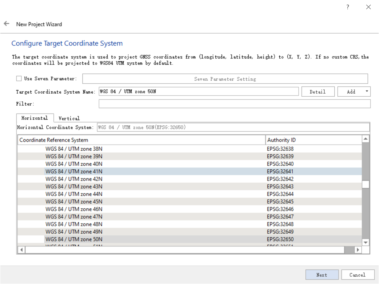
Configure Target Coordinate System
Step
1.Automatically identify the target coordinate system for the POS file imported or generated in the previous step. By default, the coordinate system of the WGS84 UTM 6-degree zone where the current collection is located is recommended.
2.If users need to modify the target coordinate system, please refer to the relevant parameter description shown below.
3.Click the Next button.
Parameter Description
- Use Seven Parameter: Use seven-parameter transformation. Click the seven parameter setting button to define the seven parameters.
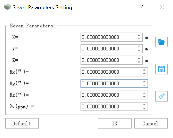
Seven Parameter Setting
- Target Coordinate System: Displays the currently selected coordinate system. You can click the Details button to view the coordinate system information in the pop-up dialog box, or you can click the Add button to add a projected coordinate system.
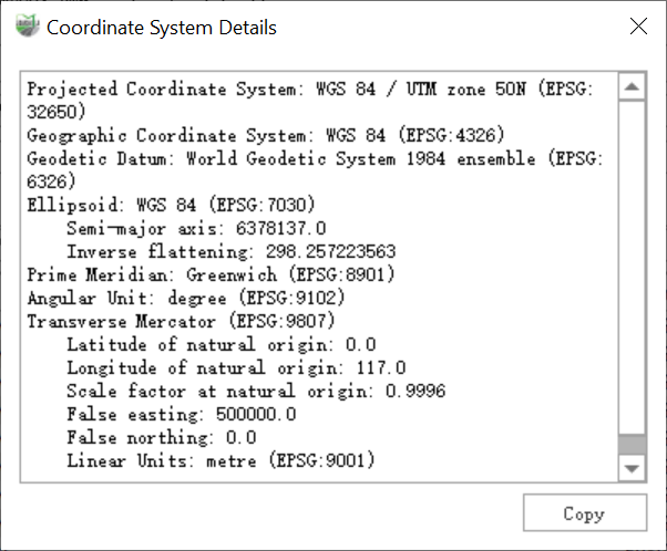
Coordinate System Details
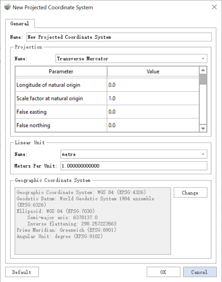
New Projected Coordinate System
- Filter: Select the coordinate system of the reprojection. By entering the keyword of the coordinate system,users can auicklv filter out the target coordinate system from the coordinate series table.
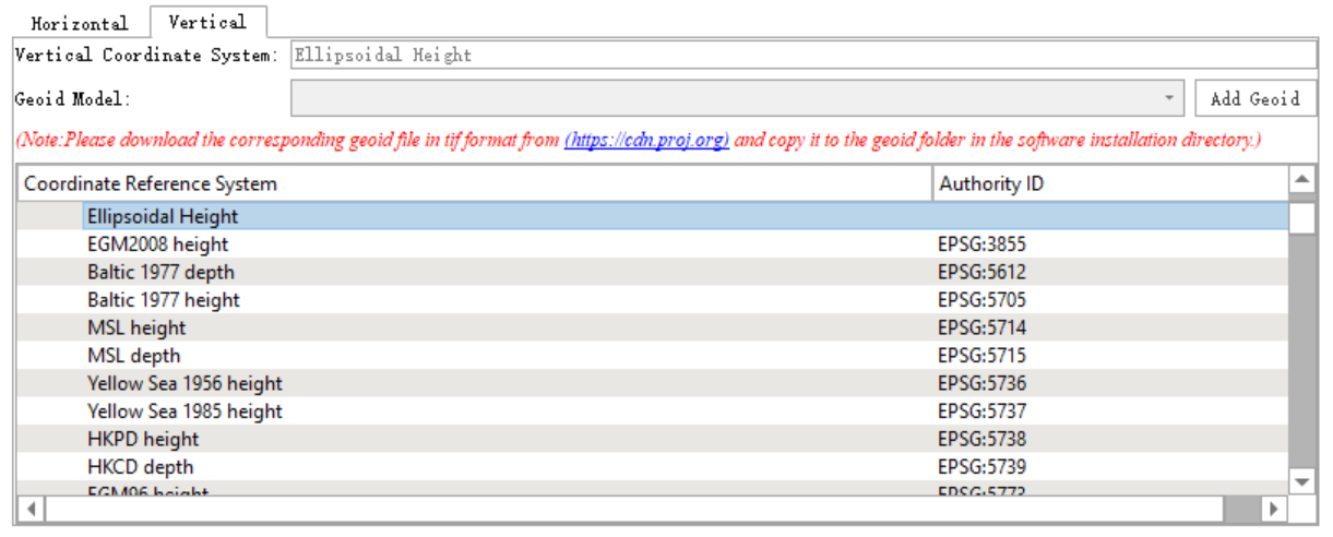
If users need to convert the vertical coordinate system, please follow the prompts to download the Geoid Model.
Vertical Coordinate System:
2.5 Configure Project Location

Configure Project Location
Step
1.Users can modify the file storage path and file name by themselves.
2.As shown in the figure, users can see the Project window in the software. The directory tree will automatically generate the *.liscan project.
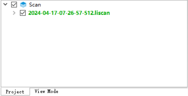
Directory Tree - Active Project
