Trajectory Adjustment
After completing Boresight calibration, if there are still layering phenomena in the point cloud, it may be due to significant trajectory errors. The strip adjustment function can post-process the trajectory and point cloud to reduce errors. Strip adjustment also supports mixed adjustment of point cloud and imagery. When the point cloud and imagery are synchronously collected data sharing the same POS system, it improves layering between point clouds and between point clouds and imagery by adjusting trajectory, exterior orientation elements of imagery, and camera installation angle errors. The imagery project file is optional; when added, it performs mixed adjustment of point cloud and imagery, synchronously adjusting trajectory, camera installation angle, and exterior orientation. Without an imagery project file, only trajectory adjustment is performed.
The strip adjustment algorithm references the works of Glira et al., 2016; Glira et al., 2019. The basic algorithm process is as follows:
- Extract point cloud surface features and normal vectors in overlapping areas of adjacent strips.
- Extract point cloud surface features and normal vectors in overlapping areas of sparse imagery points and point clouds.
- Match extracted feature surfaces in adjacent strips to obtain point cloud surface feature matching pairs.
- Match sparse imagery points and feature surfaces to obtain sparse imagery points and point cloud surface feature matching pairs.
- Establish a trajectory error correction model to calculate the distance along the normal vector of related point pairs.
Use the least squares method to minimize the distance between matching point pairs, obtaining the optimal solution.
Note:
1. Sparse imagery point clouds and laser point cloud feature matching are susceptible to noise in sparse imagery point clouds, causing mismatches. For sparse imagery point clouds with significant noise, noise filtering such as filtering power line points, sparse vegetation points, etc., is recommended.2. Sparse imagery points and the nearest laser point cloud surface features form a matching pair if certain matching conditions are met. Feature matching relies on good planar targets, including building tops, walls, and ground surfaces. In vegetation areas, it may not be possible to obtain sufficient matching features, leading to adjustment failure.@inproceedings{ author={Philipp Glira, Norbert Pfeifer, and Gottfried Mandlburger}, title={Rigorous Strip Adjustment of UAV-based Laserscanning Data Including Time-Dependent Correction of Trajectory Errors}, booktitle={Photogrammetric Engineering & Remote Sensing}, year={2016}, }
Glira P, Pfeifer N, Mandlburger G. HYBRID ORIENTATION OF AIRBORNE LIDAR POINT CLOUDS AND AERIAL IMAGES[J]. 2019. DOI: 10.5194/isprs-annals-IV-2-W5-567-2019.
Click the Preprocessing > Trajectory Adjustment button to open the strip adjustment interface.
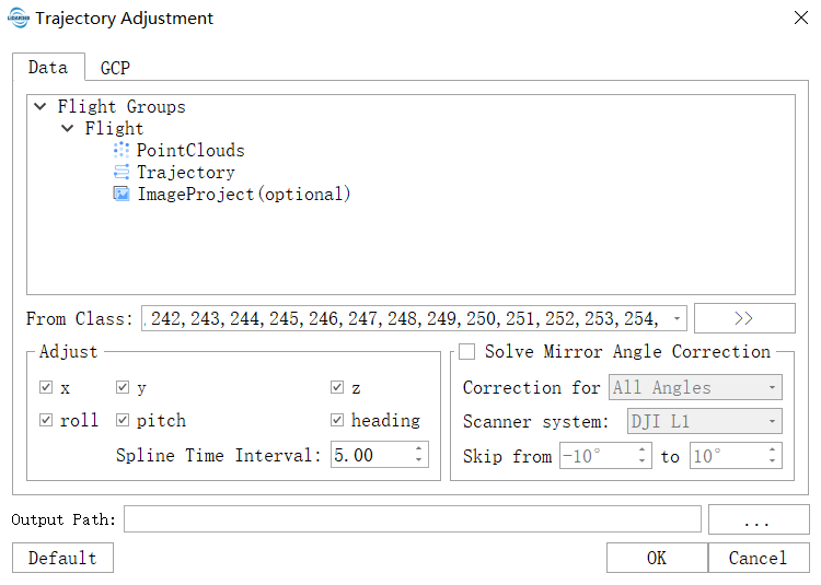
The interface has two pages: Point Clouds for inputting point clouds, trajectories, and optional imagery projects, and the GCP page for importing control point coordinate files.
Add Data
Two methods to add data:
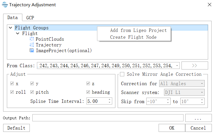
- Add from Ligeo Project: Right-click Flight Groups to import the Ligeo project file, which automatically adds point cloud and trajectory files. Since the Ligeo project file does not record the imagery project file, it must be added under the Image Project node if needed.
- Add Image Groups: Create a mission directory tree under the Flight Groups directory tree, which includes nodes for point cloud, trajectory, and imagery project. Relevant data can be imported through the right-click menu of each node.
Note: If multiple point cloud or imagery project files are imported, the file names should be unique.
Use GCP
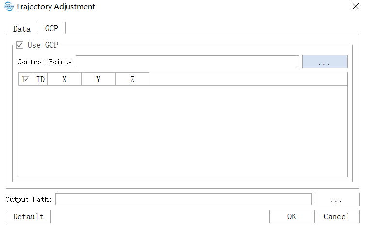
Ground control points are optional and can be used to correct elevation direction deviations. The plane features of the point cloud in the control point area are extracted, with the goal of minimizing the distance from the control point to the point cloud plane feature. The control point file must contain at least the fields: point name, X, Y, Z, and the coordinate system must match the point cloud's coordinate system.
Parameters
- From Class: The category of point cloud classification. The point cloud belonging to the selected category will be used to extract plane features.
- Adjust
- x/y/z: Position components of the trajectory correction.
- roll/pitch/heading: Angle components of the trajectory correction (roll, pitch, yaw).
- Spline Time Interval (s): The trajectory fluctuates based on the set time interval; the shorter the interval, the higher the fluctuation frequency. If the trajectory error fluctuates significantly in certain areas, a shorter interval can be set; otherwise, a longer interval can be used. The default value is effective for most data.
- Mirror Angle Correction
- Correction for: Specify the correction range for the laser scanner's scanning mirror rotation angle.
- All angles: Correct all rotation angles of the laser scanner's scanning mirror.
- Skip Centeral Part: Correct rotation angles outside the specified angle range, determined by the skip value.
- Skip from: Set the angle range of the scanner's scanning mirror that will not be corrected, and correct angles outside this range.
- Correction for: Specify the correction range for the laser scanner's scanning mirror rotation angle.
- Output Path: The storage path for the output files after the function runs. Output files include corrected point clouds, trajectories, imagery projects, and an HTML statistical report.
Note: The trajectory input for this function should ideally be the complete trajectory file from the data collection. However, if a complete trajectory file is unavailable, multiple POS files from cropped trajectories can be used, but the point cloud and trajectory GPS times must match to avoid layering phenomena in local areas after correction.
Imagery Project Settings
Imagery data and point cloud data are synchronously collected and share the same POS system. Through strip adjustment, the trajectory and camera installation angle, and exterior orientation elements are corrected simultaneously. The imagery project file must record the camera's initial installation angle, installation error, position, and roll, pitch, and heading angles at the time of image exposure. If this information is not recorded in the imagery project, it can be set in the imagery project settings dialog.
Right-click the imagery project LIAEP file to open the imagery project settings dialog:
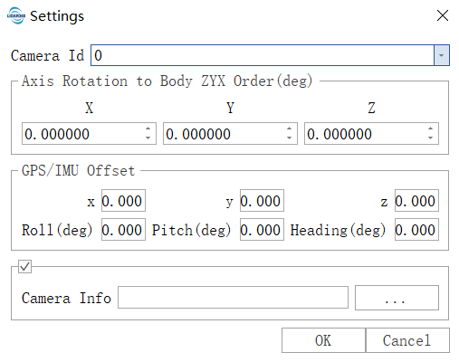
If the camera's initial installation angle, installation error, position, and roll, pitch, and heading angles at the time of image exposure are recorded in the imagery project, the corresponding values will be displayed. If not recorded, the default value is 0, and the values can be modified and updated in the imagery project file.
- Camera Id: Camera ID.
- Axis Rotation to Body ZYX Order (deg): The installation angle of the camera relative to the IMU, generally obtained from the manufacturer.
- GPS/IMU offset: Initial value of the installation error of the camera relative to the IMU.
- x, y, z: The offset of the camera relative to the IMU (m), not adjustable.
- Roll, Pitch, Heading: The installation error of the camera relative to the IMU, adjustable.
- Camera Info: Import the exposure point file of all cameras from external sources. If there are multiple camera exposure point files, they should be merged into one file for import. The file should contain at least the fields: image name, longitude, latitude, roll, pitch, heading. The program matches based on the image name. If the exposure point file is already recorded in the imagery project, it does not need to be imported.
Note:
1. The imagery project should be synchronously collected with the point cloud, sharing the same POS system.2. The coverage range of the imagery project should match that of the point cloud. If the imagery project covers a much larger area than the point cloud, there may not be enough matching pairs, leading to adjustment failure.
Mirror Angle Error Correction
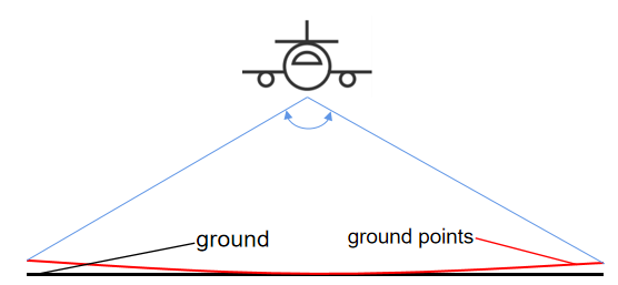
Mirror angle error refers to the scanning angle error of the laser scanner, caused by insufficient precision of scanner components or complex scanning structures. This phenomenon is more common in lightweight, low-cost scanners (such as the Risley Prism-Based Livox Mid-40). This error causes point cloud deformation, with more significant deformation at longer measurement distances, affecting the accuracy of point cloud positions and causing the cross-section point cloud along the scanning direction to curve, presenting a "smiling face" effect (as shown in smiling face). Correcting the mirror angle error can effectively eliminate the smiling face effect and improve the accuracy of the point cloud at the strip edges.
Let the coordinates of the laser point in the scanner coordinate system be $X = \begin{bmatrix} x{s} & y{s} & z{s} \end{bmatrix}^T$, the azimuth angle of the outgoing beam be $\Omega$, and the elevation angle be $\Phi$. Then $\Omega = arctan(y{s} / x{s})$, and $\Phi = arccos(z{s} / ||X||_{2})$. Since the variation in the scan angle mainly causes changes in the azimuth angle and the elevation angle is hardly affected, the scan angle error mainly manifests as an azimuth angle error. Since the scan angle error varies with the scan angle, the azimuth angle is divided into $N$ groups at $1\degree$ intervals, and the correction for the $i$th group is $\Delta_i$. Then, the coordinates of the laser point corrected for the azimuth angle in the scanner coordinate system are:
$\hat{X} = ||X||_{2} \begin{bmatrix} sin(\Omega+\Delta_i)cos\Phi & sin(\Omega+\Delta_i)sin\Phi & cos(\Omega+\Delta_i) \end{bmatrix}^T$
Mirror angle error correction is an optional function for strip adjustment. Currently, it supports DJI L1 and X3 series laser scanning systems, and it can correct all angles or angles outside a specified range.
Check Mirror Angle Correction and select DJI L1 or LiAir series according to the type of laser scanning system used. If you need to correct all angles, select All angles. You can also set the start and end angles to be skipped in the skip angle range. Mirror angle correction is performed on a flight mission basis, not on a laser scanning system basis. For multiple flight missions, if Mirror Angle Correction is checked, mirror angle correction will be performed for each mission.


If mirror angle correction is performed, the strip adjustment report report.html will output a histogram of the angle correction amounts.
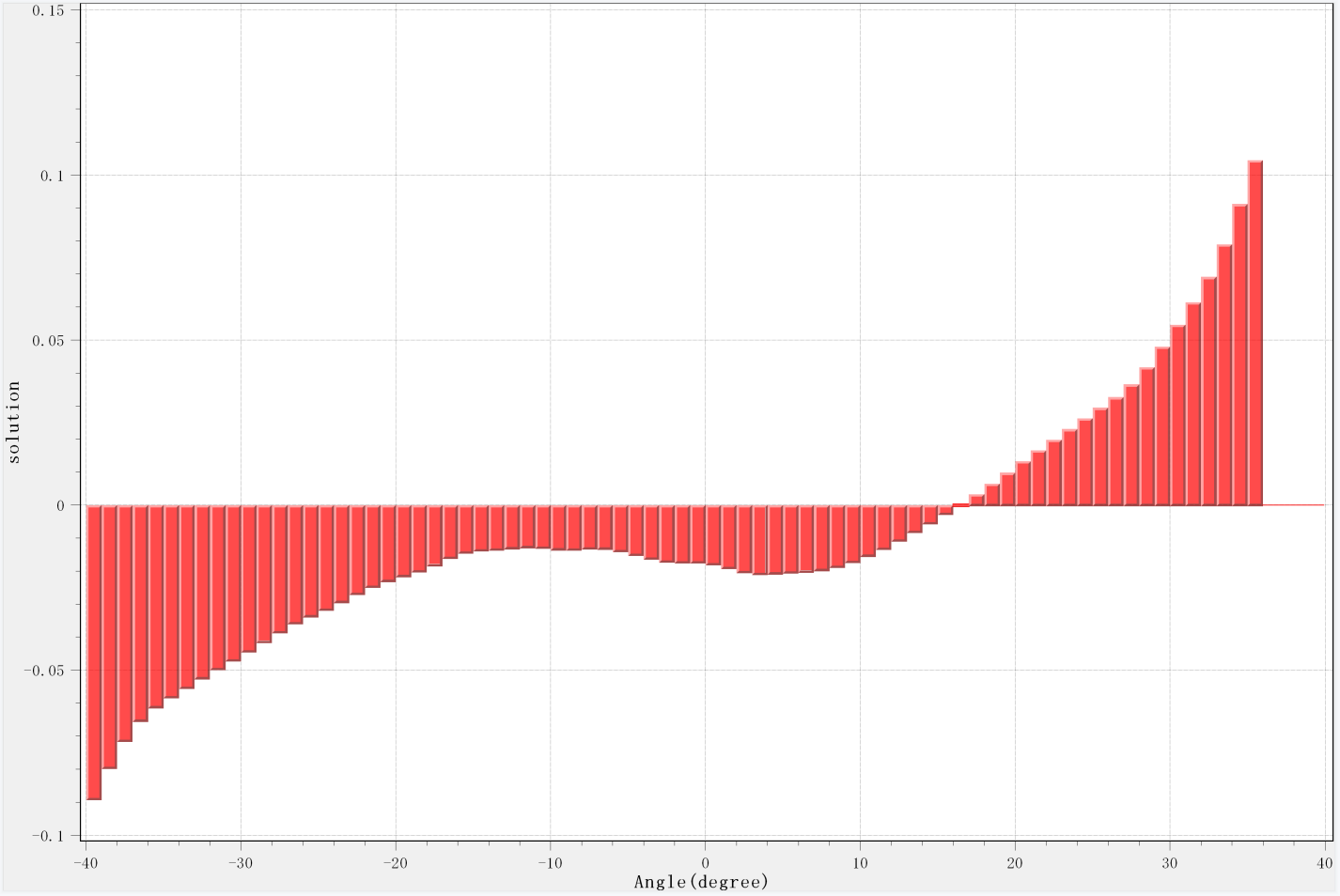
The histogram is obtained by smoothing the correction amount three times.
    @inproceedings{
        author={Brazeal, Ryan G. , B. E. Wilkinson , and H. H. Hochmair},
        title={A Rigorous Observation Model for the Risley Prism-Based Livox Mid-40 Lidar Sensor},
        booktitle={Sensors},
        year={2021},
    }
After adding all the data, click confirm, and the software will automatically perform the strip adjustment. After completion, the software will output the corrected point cloud, trajectory, image project, and statistical report, which are saved in the output path/report directory. Click report.html to open the statistical report and view the statistical charts and the updated camera installation angle errors.
Note: Each mission must add its corresponding trajectory and point cloud data, otherwise the adjustment calculation cannot be performed.
Since the corrected image project is a sparse point cloud, it cannot be effectively overlaid with the point cloud in the profile view. The corrected image project parameters can be used to generate a dense point cloud for overlaying with the laser point cloud.
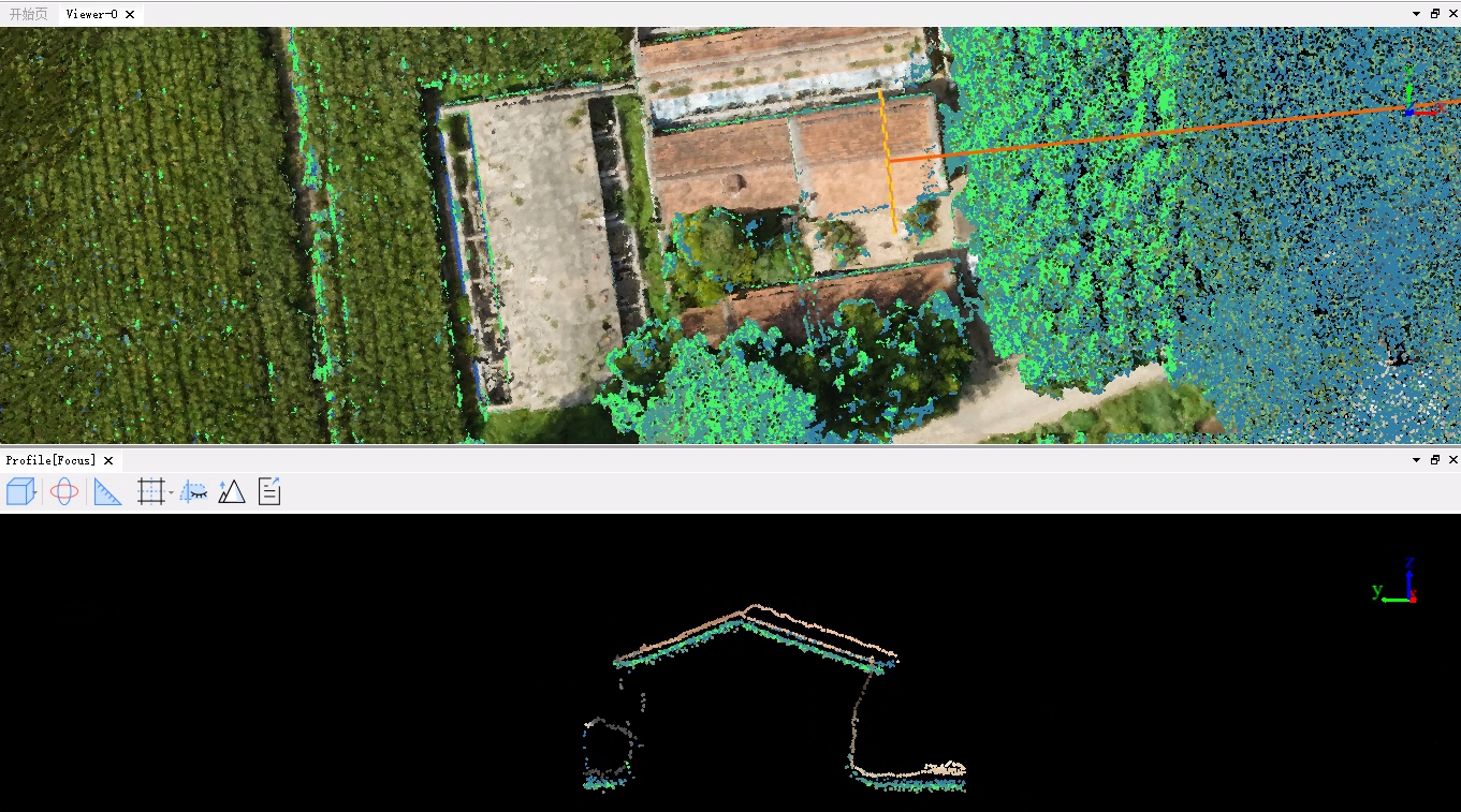
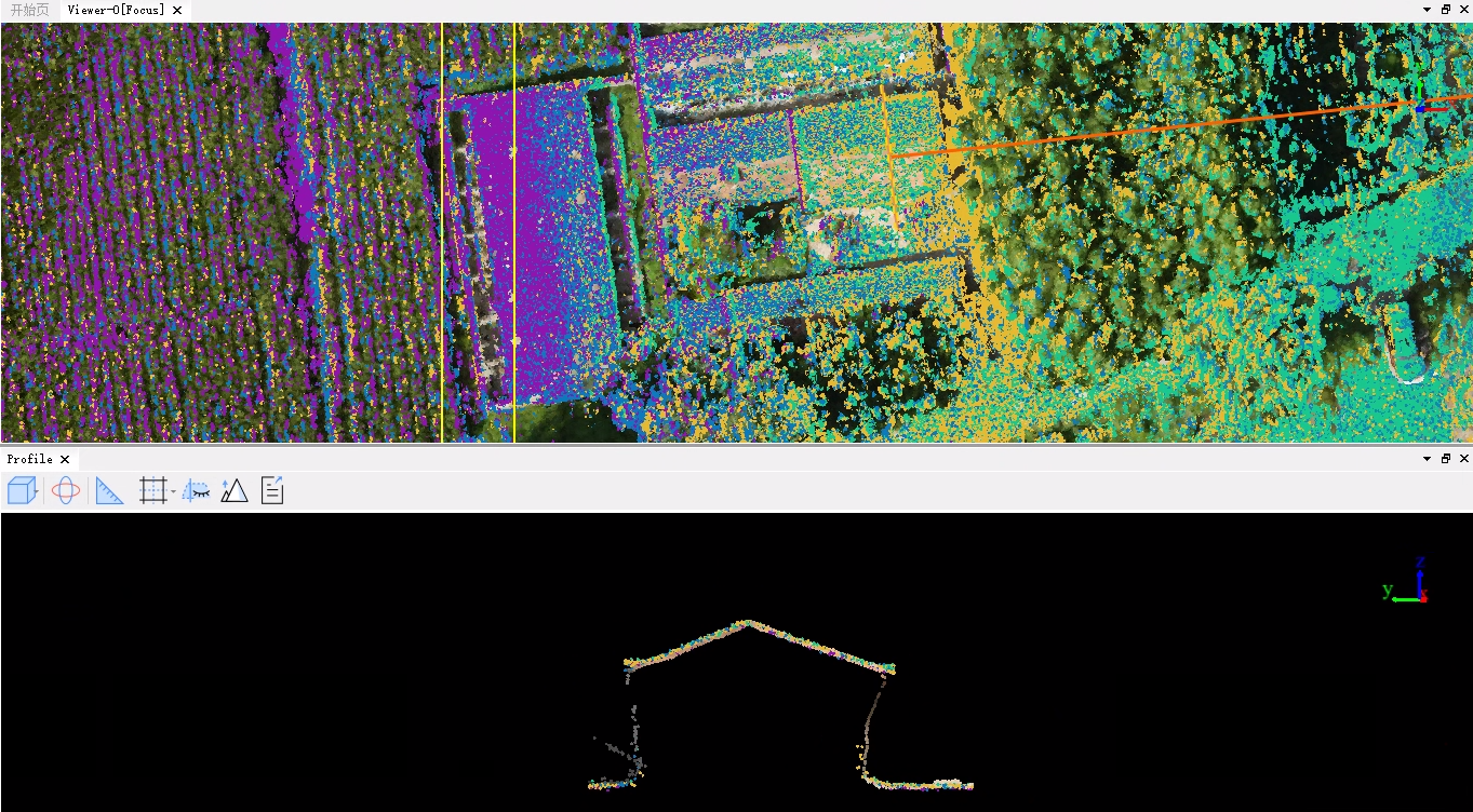
Users can use the profile tool to view the correction results of the laser point cloud, as shown in the figure.
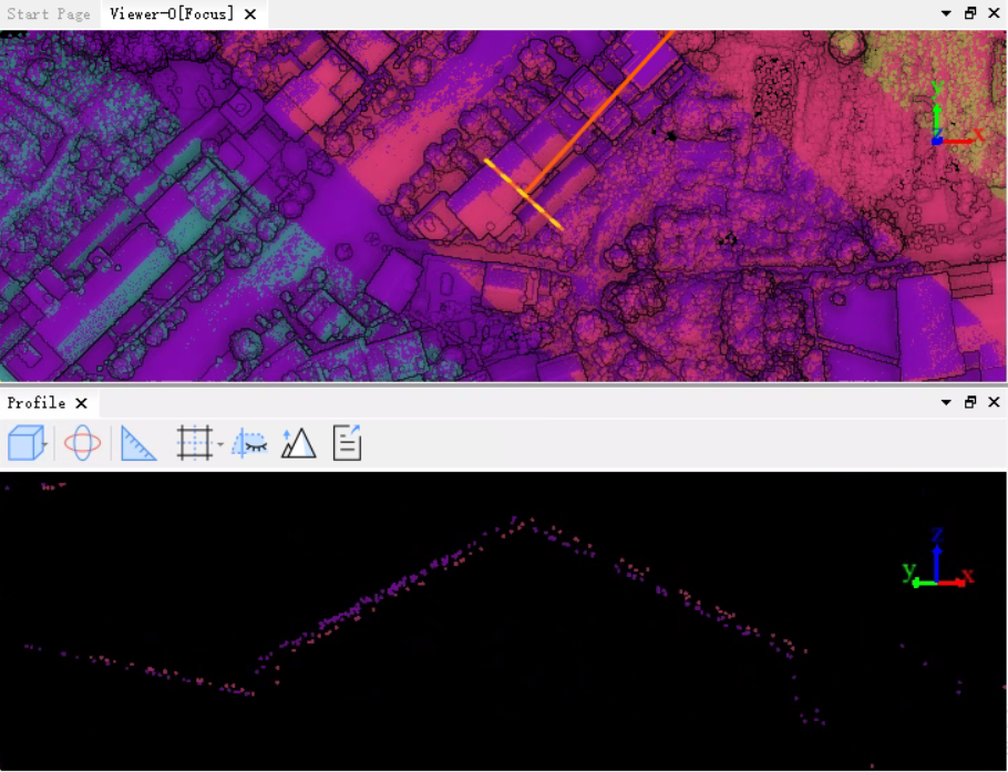
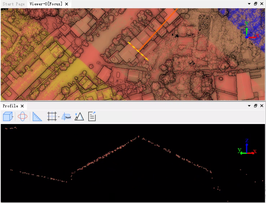
When using the image project, overlay the dense point cloud before and after correction with the laser point cloud before and after correction, and use the profile tool to view the correction effect, as shown in the figure.
Statistical Report
The content of the report varies based on the input. It includes basic information on the input data, parameter settings, trajectory maps, accuracy statistics before and after adjustment, residual histograms, scanner mirror angle error correction amounts, and camera installation error values. If only trajectory adjustment is performed, there will be no camera installation error values. If mirror angle error correction is not checked, there will be no scanner mirror angle error correction amounts.