Measure Tools
The measurement tools are used to measure geometric information of point cloud data, including single point selection, multiple point selection, point density measurement, length measurement, area measurement, angle measurement, slope measurement, height measurement, volume measurement, etc.
Icon
| Function Function Description
| |
|---|---|---|
| Pick Point | The Pick Point tool can be applied to point cloud, raster, and model data. When applied to point cloud data, it allows interactive querying of attributes of individual points, including their position, intensity, return number, classification, GPS time, etc. When applied to raster data, it enables interactive querying of attributes of individual points, including their position, stretched RGB values, pixel values, etc. | |
| Multi-point | The Multi-point tool can be used for both point cloud and raster data. It allows interactive querying of attributes of multiple points by clicking with the mouse, and supports exporting selected point sets to various formats such as txt, asc, neu, xyz, pts, csv, etc. Attributes that can be queried for point cloud data include point ID, position, classification, return number, GPS time, intensity, etc. For raster data, attributes that can be queried include point ID, position, band values, etc. | |
| Density | Point density is one of the indicators used to measure the quality of point cloud data. The point density measurement tool is used to measure the density of point clouds, calculating the average number of points per square meter. | |
| Length Measurement | The length measurement tool can be used for point cloud, raster, and model data. This tool allows interactive querying of distance information between multiple points by clicking with the mouse. For 2D data, the measurement results indicate planar distance. For 3D data, such as point cloud and model data, the measurement results indicate the Euclidean distance between points in three-dimensional space. | |
| Area Measurement | The area measurement tool can be used for all data types supported by LiDAR360. By clicking with the mouse, the tool allows interactive drawing of polygons and calculates the projected area within the polygon. For 3D data area measurement, the current window will automatically switch to orthographic projection mode. | |
| Angle Measurement | The angle measurement tool can be applied to point cloud, raster, and model data. By clicking with the mouse, the tool allows interactive selection of measurement points. In a 3D view, it queries the angle between three points, while in a 2D view, it queries the projection angle of the three-point line on the horizontal plane. | |
| Height Measurement | The height measurement tool can be applied to point cloud and model data. By clicking with the mouse, the tool allows interactive selection of measurement points and queries the relative height between two points. | |
| Gradient Measurement | The gradient measurement tool can be applied to point cloud, raster, and model data. By clicking with the mouse, the tool allows interactive selection of measurement points and queries the gradient between two points, which is the angle between the line connecting the start and end points and the horizontal plane. |
Volume Measurement
Function Description:The volume measurement tool can be applied to point cloud and model data. This tool allows interactive selection of a reference plane for measurement by selecting data from a file or by clicking with the mouse. It calculates the volumes of fill, cut, and combined cut-and-fill relative to a certain height, commonly used for applications such as measuring the volume of coal piles or ship hulls.
Steps
Click Tools > Measurement > Volume Measurement / Volume Measurement From File
- After clicking this function, a volume measurement options dialog will appear. If you choose volume measurement, set the mouse to interactively select the measurement reference plane by clicking. If you choose to select a file for volume measurement, select the file from the folder to delineate the measurement boundary. It is generally recommended to switch the view to top view before performing volume measurement.
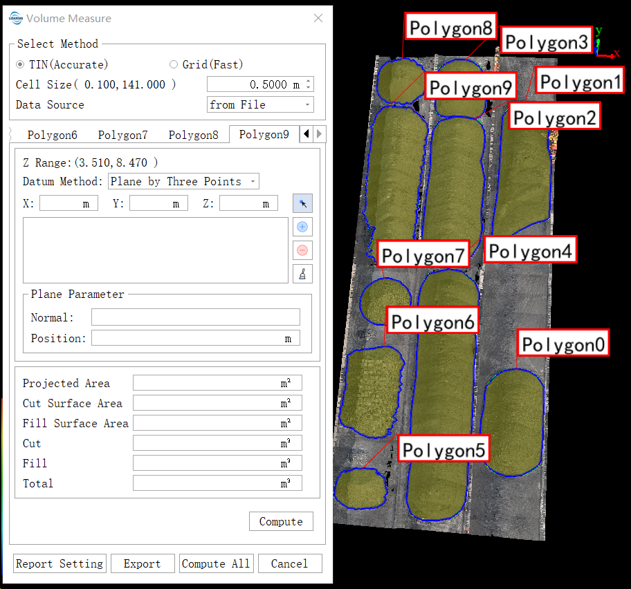
(Optional) Use the mouse to interactively select the measurement points. In the window with the loaded point cloud data, continuously click the area of interest with the left mouse button (to generate the reference plane for volume measurement, select at least three points). Double-click to finish the selection. The selected area will be outlined with a red solid line in the scene, and a dialog box as shown will appear.

(Optional) Select .shp, .dxf, or .gpkg files from the folder (currently only line and polygon files are supported).
- Set the cell size.
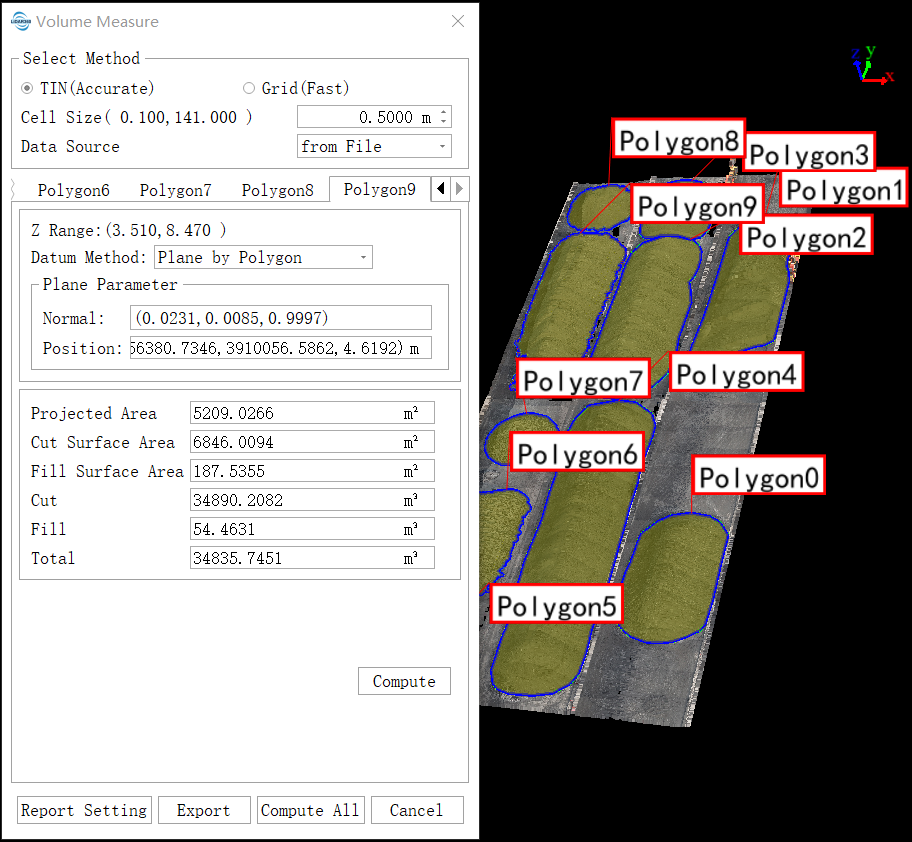
- Set the reference plane for volume measurement. The calculation methods for the reference plane include minimum value, polygon plane, custom, three-point plane, and point cloud fitted plane. Once the reference plane is determined, its plane parameters will be displayed.
- Set the data source for volume measurement. The data source types include loaded points and all points.
- Click the calculate button to generate results for projected area, surface area, cut volume, fill volume, and net volume (cut and fill). The scene will display the space occupied by the current measurement data, shown as several columns, as illustrated.

- Click the export button to export the volume measurement results in PDF format.
Parameter Settings
- Select Method: Currently supports two volume measurement methods: TIN method and grid method. The TIN method provides higher accuracy in calculation but is less efficient compared to the grid method.
- Cell Size: The grid size affects the size of the displayed columns and the accuracy of the grid method, but does not affect the accuracy of the TIN method. This parameter defines the minimum calculation unit size for volume measurement using the grid method. A smaller value provides more precise calculations.
- Reference Plane: This parameter defines the reference plane for cut-and-fill volume measurement.
- Minimum(Default): Uses the minimum Z value within the selected point range as the height value of the plane.
- Polygon Plane: Fits the best plane based on boundary points within the selected area.
- Custom: Allows the user to input or click to specify a height as the reference plane for volume measurement.
- Three-Point Plane: Determines a plane using three selected points.
- Point Cloud Fitted Plane: Determines the best plane based on selected points and a fitted region radius.
- Data Source: This parameter defines the type of data source for volume measurement.
- Loaded Points (Default): Uses points loaded within the specified range in the scene. This method is relatively faster but may be affected by changes in loaded data in the scene.
- All Points: Uses points from the specified point cloud file within the specified range. This method is slower but provides more stable calculation results.
Note: This function is specifically for volume measurement of point cloud data and can only be used in the 3D view window.
Volume Measurement on Solid Model
Calculate the volume of a closed solid model and display the result on the interface. If the model is not closed, calculation is not possible and a prompt dialog will appear. This function requires that the connection order of all triangles in the model is either all counterclockwise or all clockwise; otherwise, the volume calculation will not be accurate.
Profile View
Function Description:The profile editing feature allows users to display designated rectangular areas of point cloud data in the profile window within the main window, facilitating operations such as viewing, measurement, and classification modification.
To produce high-precision terrain products using LiDAR data, manual inspection of automatically classified results is necessary. This requires the use of profile viewing tools. Starting from version 5.0, LiDAR360 provides profile viewing functionality, which enables more efficient classification checks.