Boresight Error Calculation
The boresight error between laser scanner coordinate system and GNSS/INS coordinate system is the largest systematic error source of airborne LiDAR. The laser footprint error caused by the boresight error also depends on flight height and scanning angle.
LiDAR360 provides two approaches to eliminate the boresight error:
- Correction based on manual measurement
- Correction based on automatic adjustment
The principles of them are described as follows.
Manual Correction
Firstly, datasets for calibration need to be acquired during perpendicular and round flights (e.g., 4 flights: from east to west, from west to east, from north to south, from south to north). After data acquisition the boresight angle errors can be retrieved using the Stepwise Geometric Method(Zhang et al., 2010), which is based on measurements of overlapping laser footprints of regular objects (e.g., playground, building). Compared to angle errors, the translation errors are of less importance and hence omitted in the manual correction.
ΔRoll
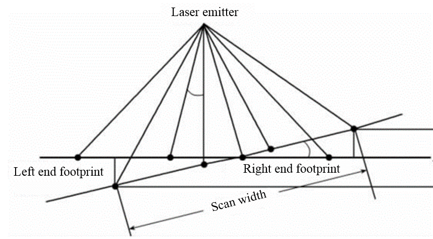
Error of Roll angle leads to an oblique result of horizontal ground, which is shown in the following figure. The planar position of scanned object is shifted along scanline (perpendicular to flight direction).

Please measure the following parameters in the data acquired during round flights of same height.
- Start a Profile Window perpendicular to the flight direction. Then measure the height difference ∆ℎ of quasi-homologous objects in two strips.
- Measure the horizontal distance r between the object and centerline of two strips in 2D-View Window.
The formula to calculate the Roll angle error is as follows:

ΔPitch
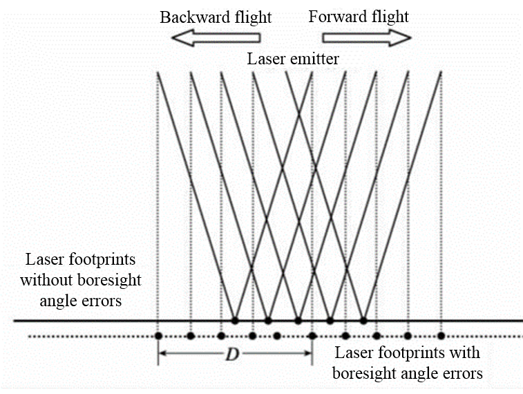
The position of scanned object is shifted along scanline due to Pitch angle error. The following figure shows the affected laser footprints.

Please measure the following parameters in the data acquired during round flights.
- Start a Profile Window along the flight direction. Then measure the distance D between centers of homologous objects along the flight direction.
- Estimate the average flight height H based on trajectory and object heights. The heights of round flights should be roughly equal.
The formula to calculate the Pitch angle error is as follows:

ΔHeading
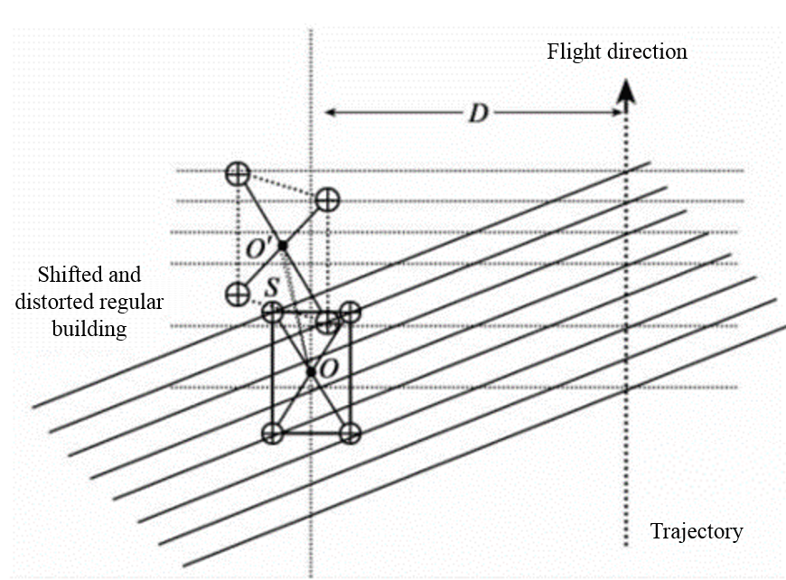
Error of Heading angle leads to object shifting and distortion. The following figure shows the erroneous result.

Please display data acquired during round flights in 2D-View Window.
- Measure the average distance S between centers of homologous objects in two strips.
- Measure the distance D between two strips.
The formula to calculate the Heading angle error is as follows:

Automatic Correction
While the manual correction relies on well-trained operators, the automatic correction can reduce manual work significantly. Based on datasets with regular objects, the automatic process can replace manual correction and achieve equivalent or even better accuracy.
The algorithm is capable of correcting not only the angle errors, but also the translation errors. Users have the flexibility to check/uncheck every correction parameter. By default, the software only calculates the angle errors, because they have the largest weights. The principle of the algorithm is as follows:
- Extract feature points and their normals in overlapping strips. Please refer to (Glira et al., 2015).
- Match the feature points to get corresponding pairs.
- Construct the correction model and calculate the distances of paired points along their normal.
- Minimize the corresponding distances using least-square method, and get the correction parameters.
    @inproceedings{
        author={Zhang Xiaohong, Forsberg Rene},
        title={Retrieval of Airborne Lidar Misalignments Based on the Stepwise Geometric Method},
        booktitle={Survey Review 42(316):176-192 April 2010},
        year={2010},
    }
    @inproceedings{
        author={Philipp Glira, Norbert Pfeifer, Christan Briese and Camillo Ressl},
        title={A Correspondence Framework for ALS Strip Adjustments based on Variants of the ICP Algorithm},
        booktitle={PFG Photogrammetrie, Fernerkundung, Geoinformation Jahrgang 2015 Heft 4},
        year={2015},
    }