Control Point Report
Summary
Control point report tool will create a report about elevation difference of laser point clouds and ground control points, which can be used to check the elevation accuracy of laser point clouds and improve the height accuracy of laser point clouds using calculated adjusted values.
Control point file is the text file separated by comma. Every row is composed by 3 columns which are X, Y and Z. At least 3 control points are requested to successfully create the control point report.
The output report displays information of elevation difference between used laser point clouds and control points of elevation, statistic information of height difference like average magnitude, standard deviation, root mean square, average of elevation difference as well as maximum and minimum height difference.
Usage
Click Strip Alignment > Control Point Report.
Select the path for the ASCII format control point file. The control point file reading settings will pop up, allowing you to set the column numbers for X, Y, and Z, as well as the number of rows to skip, and other information. You can refer to Add Data for guidance. Once the selection is complete, click Apply.
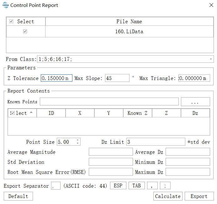
Click the Calculate button. After the calculation is complete, to view the position of each control point, double-click with the left mouse button on any position in the row where the control point is located to jump to that control point's position. You can more intuitively view the relative positions of the control points and the point cloud using the Profile Tool.

After the calculation, users can choose the control points, or change the maximum slope and maximum triangle edge length, and then click "Calculate" to re-calculate.
Settings
- Select Data: Input file can be single point cloud data file or point cloud data set.
- From Class (default value is "all class"): User needs to select the point cloud class which is used to check control point elevation accuracy, and normally point cloud of hard surface such as ground point, construction point, etc. are chosen.
- Z Tolerance (default value is "0.15"): The accuracy of the point cloud in the Z-axis direction. To avoid the distance between the points is too small leads to the excessive slope.
- Max Slope (°, default value is "45"): Maximum terrestrial gradient tolerance. If gradient is larger than this value, elevation difference will not be computed. Normally control points are chosen at the flat terrain, therefore if gradient is too steep, the result will be easily affected by wrong information.
- Max Triangle (m,default value is "20"): The longest side length of triangle is used to avoiding the large deviation caused by elevation interpolation. If the side length of triangle is too long, it is indicated that points of initial category in point cloud area where control points are located are less and calculated error of elevation difference is large.
- Known Points: Input control point file.
- Point Size (default value is "0.10"): The location of control points can be displayed in the window by double clicking the corresponding data in the list of control point report. The size of point controls the size of control points shown in the window.
- Dz Limit (default value is "3"): Set the tolerance of Dz. If Dz is not within the tolerance, show red in order to inspect elevation difference with large error between point cloud and control points. Maximum tolerance = Average Dz + Dz × Std Deviation. Minimum tolerance = Average Dz - Dz × Std Deviation.
- Export Separator:Set the exported control point report delimiter, including semicolon, comma, etc.
- Calculate: After setting parameters, click this button to calculate elevation difference.
- Export: Export the control point report file in txt format. The relevant information of the control point calculation is separated by the set delimiter. The export file contains the elevation error information of the point cloud data and the statistical information of Dz.