One-Click Workflow
Function Overview
The one-click workflow allows you to use newly created or imported image project (.liaep) files, along with point clouds or externally generated DSM/DEM images, to perform image alignment and orthoimage generation.
Note: The point cloud and image project used must be in the same coordinate system and location to execute the combined point cloud processing workflow; otherwise, the resulting product coordinates will not match, making processing impossible.
Usage

Combined Point Cloud Workflow
The combined point cloud workflow uses point clouds to generate DSM/DEM, which is then used in the image processing workflow to generate orthoimages.
- Load the point cloud and image project to be used into the window.
- Select the processes to execute based on actual needs. For orthoimage generation using point cloud DSM, it is recommended to select smoothing, resampling, denoising, DSM, image alignment, and orthoimage; for orthoimage generation using point cloud DEM, it is recommended to select smoothing, resampling, denoising, ground point classification, DEM, image alignment, and orthoimage.
- Click the run button and set the parameters for each function in the pop-up dialog box. Note that in the orthoimage parameters interface, if using point cloud-generated DSM, select DSM-based stitching; if using point cloud-generated DEM, select DEM-based stitching. Refer to other modules for point cloud parameter descriptions: SmoothPoints, Subsampling, Outlier Removal, ClassifyGroundPoints, DSM, DEM. Refer to the Parameter Settings section for image alignment and orthoimage parameters.
- Confirm that the parameters are correct, then click OK to execute the process.
Non-Point Cloud Workflow
When only completing the image alignment workflow without generating orthoimages, or when providing external DSM/DEM, you can directly perform image alignment and orthoimage workflow without using point clouds.
- Load the image project to be used into the window.
- Based on actual work requirements, only select image alignment and orthoimage workflow, and deselect all point cloud-related function buttons.
Note: The orthoimage workflow requires prior completion of the image alignment workflow or the use of an already aligned image project.
- Click the run button and set the image alignment parameters and orthoimage parameters in the pop-up dialog box. Note that in the orthoimage parameters interface, you need to select custom model stitching and set the path of the external DSM/DEM. Refer to the Parameter Settings section for other parameter descriptions.
- Confirm that the parameters are correct, then click OK to execute the process.
Parameter Settings
Image Alignment

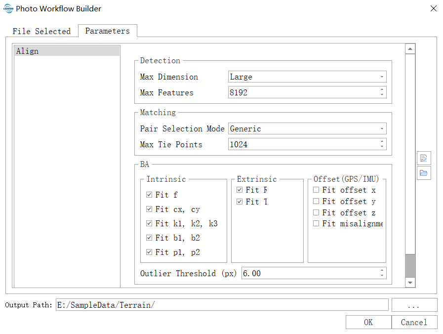
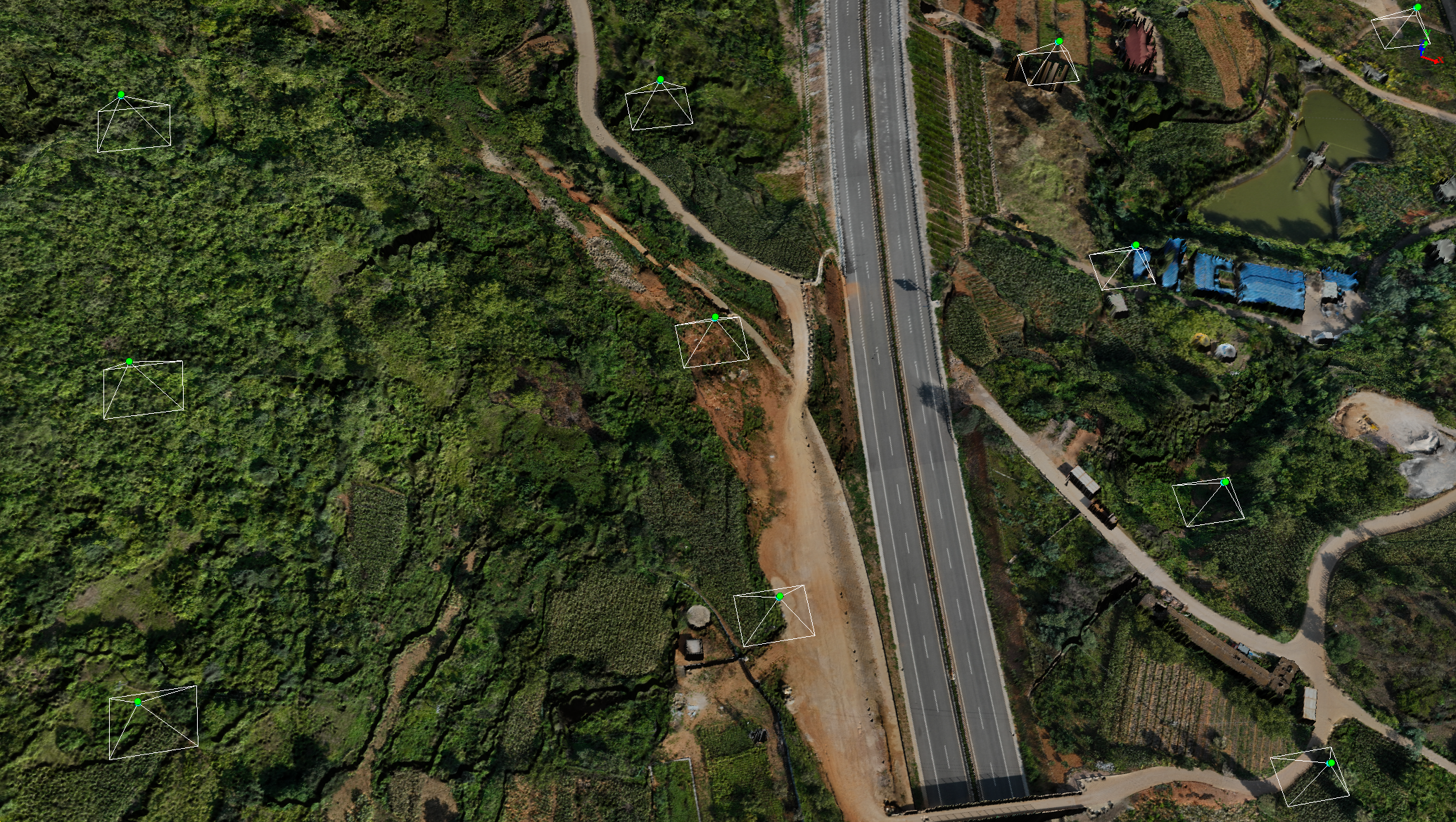
Image alignment is the process of recovering the camera's position and attitude at the time of shooting and the sparse 3D scene structure based on the original images, geographical location information (GNSS and GCP, optional), and initial camera intrinsics (optional). The image alignment results can be used for subsequent DOM/DSM generation processes.
Feature Point Detection
Maximum Image Size: There are three supported maximum image sizes: "Large," "Medium," and "Small." Depending on the selected maximum image size, different levels of sampling (up-sampling or down-sampling) will be performed on the original images during processing.
- Large (default): The large size detects the most feature points, resulting in more robust processing outcomes compared to "Medium" and "Small" sizes, and takes the longest time.
- Medium: The medium size detects fewer feature points than the large size and takes less time.
- Small: The small size detects the fewest feature points and takes the shortest time.
Note: Within a certain range, an increase in the number of feature points enhances the robustness of the processing results (too many feature points can introduce more noise). The algorithm balances processing efficiency and robustness, and in most cases, the default "Large" option yields better results.
Maximum Number of Features (default "8192"): The maximum number of features refers to the upper limit of feature points per image involved in subsequent processing steps. The higher the upper limit, the longer the subsequent processing takes, and vice versa.
Note: Efficiency should not be the only consideration, as too few features can affect the robustness of subsequent processes. The algorithm balances efficiency and robustness, and in most cases, the default value "8192" yields better results.
Feature Point Matching
Pair Selection Mode: To enhance the efficiency of feature point matching, a pre-matching image pair set is selected before the actual matching, and subsequent matching is performed only between pairs in this set. Three pair selection modes are supported: "General," "Brute Force," and "Geo-Reference."
- General (default): In "General" mode, the original images are down-sampled, and pre-matching is performed on low-resolution images to narrow down the matching range, followed by fine matching.
- Brute Force: In "Brute Force" mode, exhaustive matching is performed on all images (this process is time-consuming).
- Geo-Reference: In "Geo-Reference" mode, based on the geographical location information of the images (read from EXIF or imported externally), only the nearest subset of images is selected for pre-matching to narrow down the matching range.
Note: The "Geo-Reference Mode" is effective only when geographical location information is available. In most cases, the default "General" option yields good results. If the image alignment results are significantly incorrect, try the "Brute Force" mode.
Maximum Number of Tie Points (default "1024"): The maximum number of tie points refers to the maximum number of tie points between two images during processing. Too few tie points can affect the accuracy of the results or even cause processing failures. In most cases, the default "1024" option yields better results.
Bundle Adjustment
- Optimize Intrinsics (default: all optimized): Supported intrinsics include camera focal length (f), principal point (cx, cy), radial distortion parameters (k1, k2, k3), tangential (decentric) distortion parameters (p1, p2), and image plane distortion parameters (b1, b2). In the absence of initial intrinsics, the software's internal self-calibration algorithm can provide good intrinsic estimates. It also supports using pre-calibrated camera intrinsics. If the imported intrinsics are highly accurate, intrinsics optimization can be deselected to keep intrinsics fixed during bundle adjustment.
- Optimize Extrinsics (default: all optimized): Supported extrinsics include rotation parameters/exterior orientation angles (R) and translation parameters/exterior orientation elements (T). Without accurate externally imported camera extrinsics, be sure to select optimization; otherwise, image alignment will fail.
- Estimate Mounting Errors (default: none estimated): Supported mounting parameters include GPS mounting errors (offset values along x, y, z axes, gps -> camera) and IMU mounting errors (heading, pitch, roll angular offsets, imu -> camera). The default mounting parameters are 0 (i.e., GPS and IMU are assumed to have no mounting errors). GPS mounting errors can be accurately estimated only when GPS precision is high and accurate control points (GCP) are available. If GPS precision cannot be guaranteed or there are no control points, do not select this option, as it will severely impact the alignment results.
- Outlier Threshold (default "6.00"): The outlier threshold is the upper limit of reprojection error during bundle adjustment (in pixels). Feature points and their corresponding scene points exceeding this threshold will be excluded to effectively suppress the impact of outliers on the adjustment results.
Mosaic

The orthoimage process utilizes the interior and exterior orientation elements of the images and the generated Digital Elevation Model (DEM) or Digital Surface Model (DSM) to orthorectify the original images and stitch and merge the corrected images. The module involves processes such as distortion correction, orthorectification, image exposure compensation, color enhancement, image stitching, and merging.
Generation Modes
The generation modes include three types based on the data source: generated DSM, DEM, and externally imported data. Generally, DSMs have higher precision, making it easier to restore correct pixel positions during orthorectification, resulting in higher-quality orthoimages. For example, in urban areas with significant building height differences, using DEM-generated orthoimages often results in tilted buildings, whereas in relatively flat areas, the effect of using DEM or DSM for orthorectification may not differ significantly.
- DSM-based stitching: Stitch orthoimages based on DSM generated from point clouds. In most cases, it is recommended to generate DSM and use this mode for the best results.
- DEM-based stitching: Stitch orthoimages based on DEM generated from point clouds. This mode is effective in forests with tall tree canopies. Since DEM is used, the positional accuracy of ground objects in the orthoimages may decrease.
Custom model stitching: Use custom DEM or DSM for pixel-by-pixel stitching; DSM is recommended.
Note: 1) In combined point cloud workflows, a corresponding DEM or DSM must be generated, or users can import the corresponding DEM or DSM; otherwise, the
process will be interrupted due to lack of data. 2) The coordinate system of the imported DEM or DSM will be automatically converted to the current project coordinate system; otherwise, it needs to be set during import.
Parameter Options
- Fusion Level (default: high): Includes five options: "High," "Medium," "Low," "Very Low," and "None," where "None" means no fusion. When the width and height of a single orthoimage are large (exceeding 3000 x 3000 pixels), the higher the fusion level, the better the fusion effect. When the generated orthoimages are small (less than 1000 x 1000 pixels), a high fusion level can easily lead to overall darkening, in which case, lower the fusion level appropriately. Color correction (default enabled): If enabled, the module will readjust the brightness, contrast, saturation, and white balance of the original images during orthorectification. In most cases, enabling this feature helps generate clear, well-lit, and vibrant orthoimages. If the input images are multispectral, this feature is disabled.
- Maximum Tilt Angle (default 60 degrees): Images with tilt angles greater than this value will be excluded from orthorectification, stitching, and merging. Images with smaller tilt angles are preferred as they produce better quality orthoimages and consume less computational resources, resulting in higher efficiency.
- Resolution: This parameter defines the spatial resolution of the output DOM (unit: meters). The smaller the value, the higher the resolution, and the longer the processing time.
- Occlusion Detection: This parameter determines whether to perform occlusion detection during orthorectification. For urban oblique photogrammetry scenarios, it is recommended to enable this option to reduce occlusion caused by buildings. For forest data combined with point clouds, due to the penetration capability of LiDAR, the generated DEM/DSM, etc., may not require occlusion processing, so it is recommended to disable this option.