Add Data
Functional Description: Data types supported by LiDAR360 include point cloud, raster, vector, table, model, trajectory and aerotriangulation project.
LiDAR360 supports point cloud data formats including LiData (*.LiDataProprietary LiData File), LAS (*.las,*.laz), ASCII (*.txt, *.asc, *.neu, *.xyz, *.pts, *.csv), PLY (*.ply), E57(*.e57), PCD(*.pcd).LiData is a customized point cloud data format. All analysis and processing operations related to point clouds are based on this format. After importing point cloud data in LAS, ASCII, PLY, E57, PCD and other formats into the software, the corresponding LiData format will be automatically generated.
When loading data for the first time, data will be converted into LiData format which can support efficient browsing and processing of massive data according to the pop-up loading interface and different requirements of users.
ClickFile->Data->Add Data (in addition, you can also click) to bring up the Add Data interface.
Add LAS Data
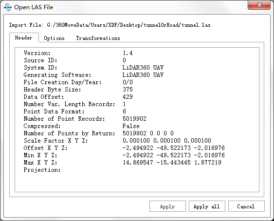
Select the LAS file to be loaded, the first load will bring up the screen shown in the following figure. The top of the screen shows the path of the LAS data to be opened. The Header tab describes the information about the LAS header file.Contains the LAS data version number, source ID, system identifier, generating software, file creation date, file header size......From the start of the file to the first point data record the number of bytes of the first field, the number of variable length records, the point data format ID, the number of point data records, whether to compress, the number of points of each echo count, X/Y/Z scale factor, X/Y/Z offset, the minimum X/Y/Z coordinates, the maximum X/Y/Z coordinates and other information.
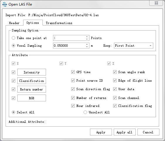
Thinning The option tab allows you to thin the point cloud when it is opened. Thinning supports two modes. Spatial thinning and voxel thinning.
- Take one point at n Point (default "1"): Import one point every n points.
- Voxel Sampling: The voxel thinning method reduces the point cloud density by removing some points that are close to each other or within a grid cell of a given size. Firstly, the mesh is refined based on 3D gird, and then a point in the grid is retained with the corresponding strategy.
- Voxel size (default: 0.05): Grid cell size for voxel sampling.
- Keep (default: "first point"): Used to determine how the algorithm preserves points entering the grid. See the table below for methods and descriptions.
| Reserve the point policy | description |
|---|---|
| First point | The first point to enter the voxel is reserved |
| Highest point | The highest point in the voxel is reserved |
| Lowest point | The lowest point in the voxel is reserved |
| Median Z Point | Points in the grid whose Z value is in the middle position are reserved |
| Average Point | The average point is the average of all the points in the voxel |
| Voxel Center point | Keep the center of the voxel, not the point cloud |
| Highest Intensity | The most reflective points in the voxel will be retained |
| Lowest Intensity | The least reflective points in the voxel will be retained |
| Max GPS Time | The latest point in the voxel is reserved |
| Min GPS time | The earliest point in the voxel is reserved |
Attribute selection. Select attributes and additional attributes of LAS data. By default, all properties of LAS data are imported.
Select a coordinate system or coordinate conversion. You can define coordinate system for point cloud data, or do re-projection or custom coordinate transformation. The corresponding coordinate system can be quickly found by inputing the keywords of coordinate system, or click the drop-down menu of add coordinate system button and import coordinate system from WKT or PRJ. Refer to Reprojection.
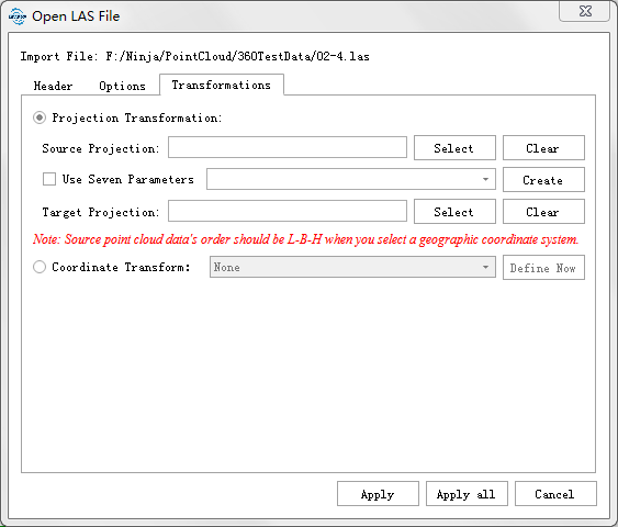
Projection transformation.
- Source coordinate system. If the user only selects the "source" coordinate system, the "source coordinate system" will be defined by the imported point cloud and overwrite the existing coordinate system of the Las file. Similar to the function "Define Projection".
- Target coordinate system. If the user has selected the "source" coordinate system, the "target projection" can also be selected to complete the reprojection operation. When the user selects the target coordinate system, the "source" coordinate system must be selected.
Coordinate Conversion.
- Users can define and apply coordinate conversion relationships such as seven-parameter, four-parameter, 3D affine conversion, XYMultiply, and linear conversion to point clouds. Refer to creating a transformation relationship.
ClickApplyto import the selected LAS data into the software using the current settings, and start to load the point cloud. If you selectApply All, this setting will also be adopted for other LAS data that you imported before closing the software, and the dialog box for opening LAS data will not pop up again.
Import TXT File
- Select the TXT file to be loaded, and the interface as shown in the following figure will pop up:
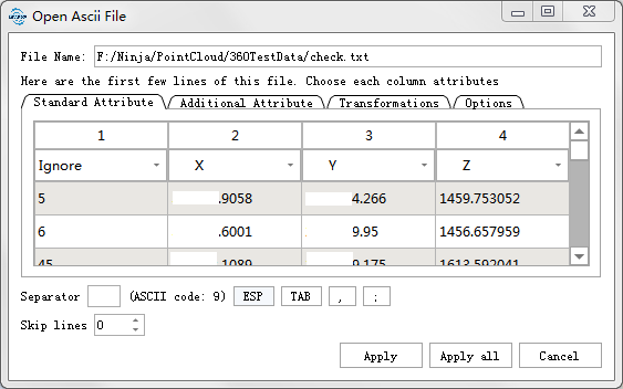
The data path to be opened is displayed at the file name, and if there is a header in the data, the header line is highlighted in red. Open the additional attribute page, check the required additional attribute information, double-click the column name of "Attribute name" to edit the additional attribute name, and select the data type of the additional attribute. Currently, only Integer and real data types are supported for ASCII data.
Delimiter. In general, the software can automatically identify the Separator of a file and the user can select the corresponding Separator in the separator column.
Skip data: File headers and other unwanted data can be ignored by skipping line X on the Skip lines.
Data selection: The software will select the column where X, Y and Z are located by default. The user can click the drop-down button above each column to select the corresponding attribute of the data in each column. Select Ignore to ignore the column data, which can be imported as an additional attribute.
- Click the additional attributes page and select the additional attributes to be imported. The attributes can be renamed. Double-click the corresponding attribute name in the "Attribute name" column for modification. The types of additional attributes support integers and reals.
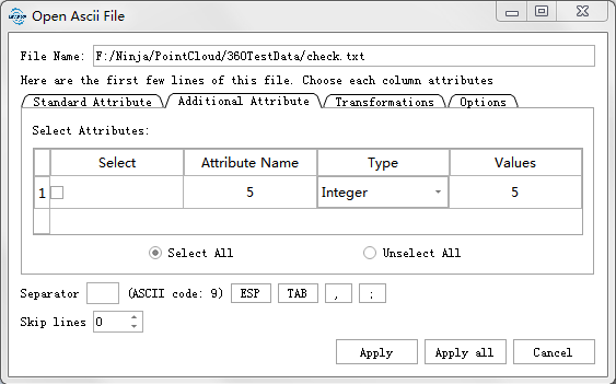
- Thinning Refer to "thinning" in LAS Data.
- For coordinate system and coordinate conversion options, see "Select Coordinate System or Coordinate Conversion” in Add LAS Data.
Import CSV File
Select CSV data to load and the interface as shown in the following figure will pop up:
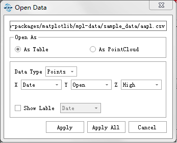
CSV data can be optionally opened as a table or a point cloud.
In general, if the CSV file is generated by tree segmentation, you are advised to open it as a table. The data type can be points or circles. If you select the point mode, specify the columns corresponding to X, Y, and Z. If you choose to display in a circle, in addition to X, Y, and Z, you also need to specify the columns corresponding to the diameter of the circle:
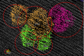
The Display label’s check box determines whether to display labels of each point or circle in the software. If you select display labels, specify columns corresponding to the labels, for example, ID of the segmented tree. If you select open as a point cloud, it will pop up the same page as that displayed for opening TXT data. For details, see the description of adding TXT data.
Import PLY File
Select CSV file to load and the interface as shown in the following figure will pop up:
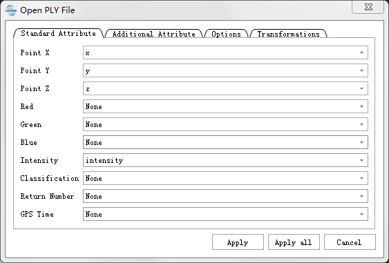
Specify the attributes corresponding to the X, Y, and Z coordinates.
Select the corresponding fields if there is Intensity information, and select the attributes corresponding to R, G, and B if there is color information. If not, select None.
- Click the additional attributes page. If the PLY file has Normal X,Normal Y. Then you can import the Normal information as an additional attribute, and other additional attributes are displayed in the list. Choose the selected information to generate related additional attributes.
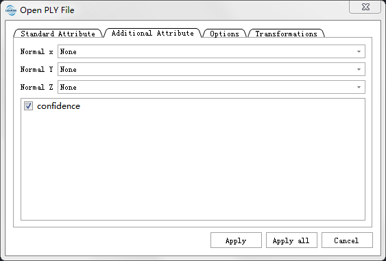
- For coordinate system and coordinate conversion options, see "Select Coordinate System or Coordinate Conversion” in Add LAS Data
- Thinning Refer to "Thinning" in LAS Data.
- After setting, clickApply.
Import E57 File
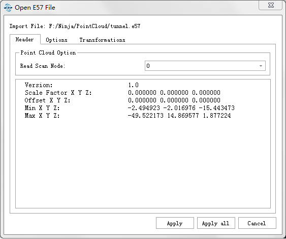
Select the E57 file to be loaded.When loading for the first time, the interface as shown in the following figure will pop up. The top of the interface displays the path of E57 data to be opened. The Header tab describes the E57 header file information, including the name of the scanned data node of E57 data, the version number, the XYZ scaling factor, the offset, and the surrounding box information.
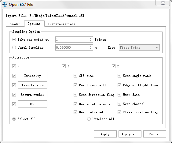
In Option tab, you can select to thin the point cloud when it is opened and open all points by default. You can also select the attributes of E57 data and additional attributes and import all attributes of E57 data by default.
For coordinate system and coordinate conversion options, see "Select Coordinate System or Coordinate Conversion” in Add LAS Data
Thinning Refer to "Thinning" in LAS Data.
ClickApplyIndicates that the selected E57 data is imported to the software using the current settings, and loading the point cloud . If you chooseApply All, this setting is adopted for all data opened this time. The E57 data opening dialog box will not pop up again until E57 data is opened again.
Import PCD File
LiDar360 supports the reading of several PCD fixed fields:
| The PCD field | corresponds to the attributes read into 360 |
|---|---|
| x/y/z | x/y/z |
| normal_x | Additional attribute - The x-component of Normals |
| normal_y | Additional attribute - The y-component of Normals |
| normal_z | Additional attribute - The z-component of Normals |
| intensity | Intensity values |
| rgb | r, g, b components of rgb point cloud |
Select the PCD file to be loaded. The interface shown in the following figure will pop up when the PCD file is loaded for the first time.
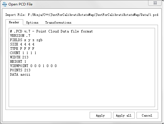
In Option tab, you can select to thin the point cloud when it is opened, and open all points by default. You can also select the attributes of PCD data and additional attributes, and import all attributes of PCD data by default.
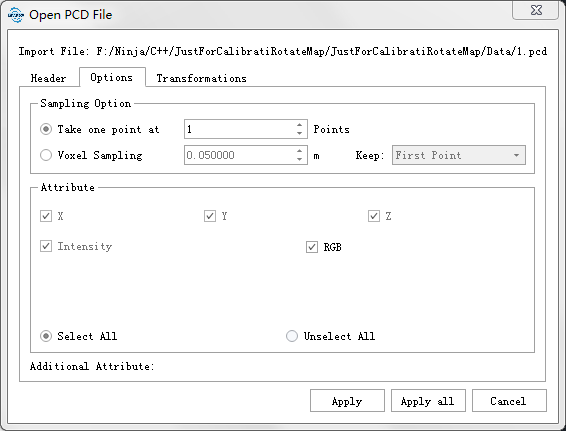
For coordinate system and coordinate conversion options, see "Select Coordinate System or Coordinate Conversion” in Add LAS Data
- Thinning Refer to "Thinning" in LAS Data.
Import Raster File
Raster file is a data form that divides the space into regular grids, each grid is called a cell, and assigns corresponding attribute values to each cell to represent the entity. In its simplest form, a raster consists of a matrix of cells (pixels) organized into rows and columns (grid) where each cell contains a value representing information. The position of each cell (pixel) is defined by its row number, and the entity position represented is implicit in the raster row position. Because of this, it is often easy to write efficient code quickly while doing data analysis.
Click File > Data > Add Data.
Select the raster data to be loaded and click open.
Import Vector File
Vector data can be represented in its original resolution and form, graphical output is often more aesthetic (compared to traditional map representation), it doesn’t require data conversion, and can maintain accurate geographic location. .shp, .dxf, and.kml formats are supported.
Click File > Data > Add Data.
Select the vector data to be loaded andclick open.
Import Model File
LiDAR360 support Model data formats including Model (*.LiModel,*.LiTin,*.LiBIM,*.LiTree), OSG data(*.osgb,*.ive,*.desc,*.obj), DXF File (*.dxf), among which LiModel file generates regular triangulation model according to DEM or DSM, saves regular grid dot, organizes and stores regular triangulation model in blocks according to quad-tree, and can also superimpose DOM texture information on it. LiTin file is an irregular 2.5D triangulation model generated according to the point cloud. It is colored according to the elevation, and the light and shadow effects are used to improve the display effect. It can be flat, delete, add vertexes, increase the fracture line and other editing, improve the quality of contour generated according to it. LiBIM is a building model based on the point cloud. LiTree is a tree model file generated based on individual tree information.
Click File > Data > Add Data.
Select the model data to be loaded andclick open.
Note: LiDAR360 supports drag and drop to add data. If it doesn't work, click here to see more.
Import Trajectory File
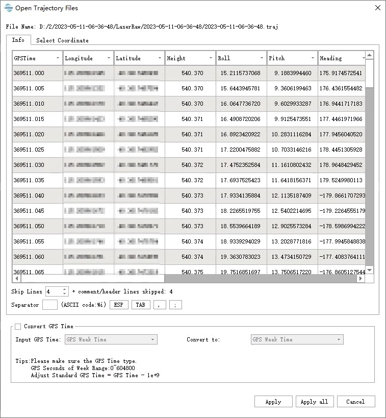
Currently, LiDAR360 supports three types of trajectory files(*.traj、*.pos、*.out)。
For traj and pos formats, the fields to be set, including field order, skip lines, and delimiter. In the fields, the required fields include GPS time, longitude and latitude (or GridX, GridY), height, Roll angle, Pitch angle, and Heading angle. For the *.out format, no fields need to be selected.
If the GPS time of the input point cloud data is SOW(seconds of aweek), it needs to be converted to GPS Time. The acquisition date of the input data calculates the GPS week number internally, firstly calculates the GPS standard time, and then subtracts 109 from the GPS Coordinated Universal Time.
When the longitude and latitude fields are set but the GridX and GridY fields are not set, the coordinate system to be converted needs to be set on the coordinate system selection page. The recommended default coordinate system is the corresponding WGS 84 UTM projection coordinate system for the longitude. If set at the same time, the GridX and GridY will be used directly as the projection coordinate values without projection transformation. The out format trajectory file only contains longitude and latitude information, so a coordinate system also needs to be set. The method for setting the coordinate system can refer to the Define Projection page.
Import aerotriangulation Result
The aerial triangulation results in LiDAR360 contain both interior and exterior orientation elements of the images, and some formats also contain tie point information. LiDAR360 currently supports several formats for aerial triangulation results, including internal formats (.LiAep), LiMapper projects (.limap), LiGeoreference projects containing images (.ligeo), BlocksExchange xml format (.xml), Pix4d projects (.p4d), and Inpho projects (.prj). When a format other than the internal image project is selected, it will be converted to the internal image project (*.LiAep) for use in other functions.
Note:LiDAR360 supports adding this type of data directly by drag and drop. If dragging and dropping does not work, click here to see more.