Define Projection
Summary
Define a coordinate reference system for point cloud data. The coordinate reference system generally includes geographic coordinates (usually latitude and longitude coordinates), geocentric coordinates and projected coordinates (plane coordinates converted by projection). This feature supports defining geographic and projected coordinates for point cloud, raster, vector files.
Usage
Click Data Management > Projections and Transformations > Define Projection
Settings
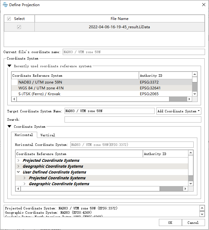
Select Data: Input one or more point cloud data files. File format: .LiData, .tif, .shp, .gpkg.
Current File's Coordinate name: Displays the name of the coordinate system defined for the current point cloud.
Target Coordinate System: Displays the name of the currently set coordinate system, allowing for custom coordinate system names.
Detail: Displays detailed information about the currently set coordinate system.
Add: Users can add coordinate systems from external sources or create custom coordinate systems. LiDAR360 software provides three methods to add external coordinate systems:
- Add Geographic Coordinate System
- Add Projected Coordinate System
- Add Vertical Coordinate System
Filter: Users can input the defined coordinate system by entering keywords related to the coordinate system, corresponding systems can be filtered from the World Coordinate Systems list (e.g., to set the point cloud coordinate system to WGS 84 / UTM Zone 49N, you can enter "UTM 49N" in the filter option for quick selection, or enter its EPSG code: 32649 for rapid searching). Alternatively, you can click the Add button to import coordinate systems from external sources.
Set Coordinate System: Select the coordinate system to be set, which can be selected from the default coordinate system or a custom coordinate system. First, select the horizontal coordinate system on the Horizontal tab. At this time, the vertical coordinate system defaults to the height of the ellipsoid. If you need to define a vertical coordinate system, you can switch to the Vertical tab to select a vertical coordinate system, and the two together form a combined coordinate system.The coordinate system selection interface includes the following sections:
Recent: Records the coordinate systems recently used.
- Favourites: Shows coordinate systems added to favorites.
- Projected Coordinate Systems: Includes all default projected coordinate systems.
- Geographic Coordinate Systems: Includes all default geographic coordinate systems.
- User Defined Coordinate Systems: Includes all custom coordinate systems.
- Layers: Includes coordinate systems from loaded data.
- Vertical Coordinate Systems: Includes all default vertical coordinate systems.
- User Defined Vertical Coordinate Systems: Includes all custom vertical coordinate systems.
- Layers: Includes coordinate systems from imported data, grouped by coordinate system name.
Right-click any coordinate system and select the Add to Favourites option from the context menu to add the selected coordinate system to your favorites. To remove a coordinate system from favorites, right-click the favorite system and choose Remove from Favourites.
Delete: Right-click on any custom coordinate system and select the Delete option to remove it. If the deleted custom vertical coordinate system is used in any custom combined coordinate systems, you will be prompted to decide whether to delete the combined coordinate systems as well. Choosing "Yes" will delete all associated coordinate systems, while "No" will leave the combined coordinate systems unaffected.
Copy and Modify: Right-click on any coordinate system and select the Copy and Modify option to modify the coordinate system parameters and save it as a new custom coordinate system. This action will pre-fill the modification interface with the parameters of the currently selected coordinate system. For detailed settings, refer to the section on adding coordinate systems.
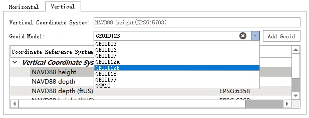
Set Geoid Model: On the Vertical tab page, the user can set the geoid model of the vertical coordinate system. If the user need to use this option, the user need to provide the vertical reference grid data. For the method, please refer to the next section Vertical Coordinate System. At present, this setting has the following three situations.
- When this option is not set, if the vertical datum grid data is provided, the appropriate geoid model will be automatically searched and used during coordinate transformation. If not provided, the geoid model will not be used during coordinate transformation (except for the EGM2008 model included in the software installation package).
- If the selected vertical coordinate system can use the geoid model supported by default, it can be selected from the drop-down list, and the model will be specified when performing coordinate transformation. For the geoid models currently supported by default in LiDAR360 software, please refer to the Geoid Model page.
- If the geoid model to be used is not included in the package provided by PROJ, the user can place the model file to be used under the geoid folder in the software installation directory, and then add the geoid model by clicking the Add Geoid button to add the file (support tiff and gtx formats), the model will be added to the drop-down list, after selecting the added model, the custom geoid model will be used in the coordinate transformation process.
If the coordinate range of the selected geoid model does not match the coordinate range after point cloud coordinate transformation, the model will not take effect.
Selected Coordinate System: The information of the coordinate system selected by the user will be displayed here.
After clicking OK, the WKT information representing the projection will be written to LiData.
Vertical Coordinate System: Users can customize the vertical coordinate system. Vertical coordinate system transformations and grid projections require vertical datum grid data for valid transformations. EGM2008 geoid model elevation conversion is provided by default in the software. If you need to support other regional geoid models, you need to download the corresponding grid data files. The grid files are provided by the official PROJ library, which can be downloaded here proj-data-1.8, or on the official website https ://proj.org/download.html to download the latest version of proj-data. After downloading, unzip the file to the geoid folder in the software installation directory, the default is C:\Program Files\GreenValley Suite\LiDAR360\5.0.0.0\geoid, "5.0.0.0" is the version number, and there will be differences between different versions.Download the corresponding geoid file (TIF format) from https://cdn.proj.org/ and copy it to the geoid folder in the software installation directory. When using, strictly comply with content providers' requirements and applicable laws of the region where the information originates.
Note: The custom geoid model must be placed in the geoid folder to take effect.
Add Geographic Coordinate System
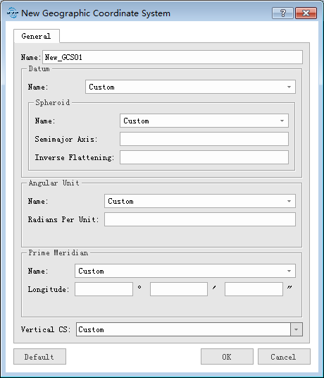
- Name: Users can customize the name of a geographic coordinate system .
- Datum:
- Name: Users can customize a datum name or select a known datum from the drop-down list.
- Spheroid: If a user selects the datum from the drop-down list, the ellipsoid parameter does not require to be entered.
- Name: The name of the spheroid.
- Semimajor Axis: Spheroid's major semiaxes.
- Inverse Flattening: Inverse flattening of the spheroid.
- Angular Unit:
- Name: Users can customize the angle unit name, or select the angle unit name from the drop-down list.
- Radians Per Unit: Define the unit of arc in the geographic coordinate system.
- Prime Meridian:
- Name: Users can customize the name of the central meridian, or select the name of the central meridian from the drop-down list.
- Longitude: Enter the central meridian longitude.
Add Projected Coordinate System
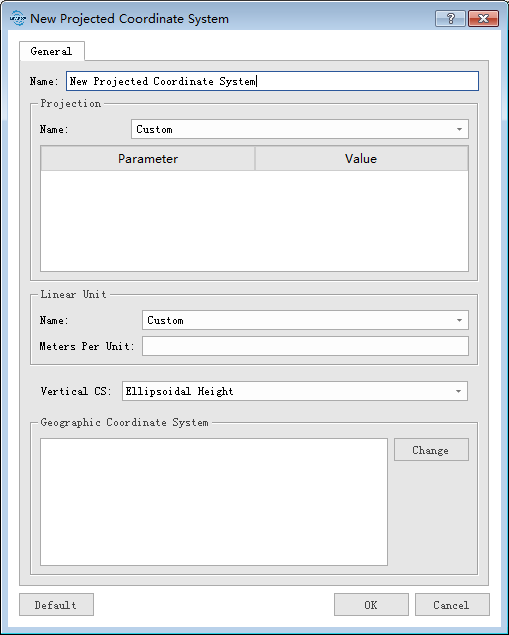
- Name: Users can customize the name of a projection coordinate system.
- Projection:
- Name: Users can customize a projection name or select a known projection from the drop-down list. It should be noted that user-defined projections can be modified from a projection template selected from the drop-down list.
- Linear Unit:
- Name: Users can customize the linear unit name or select the linear unit name from the drop-down list.
- Meters per Unit: Input meters per unit.
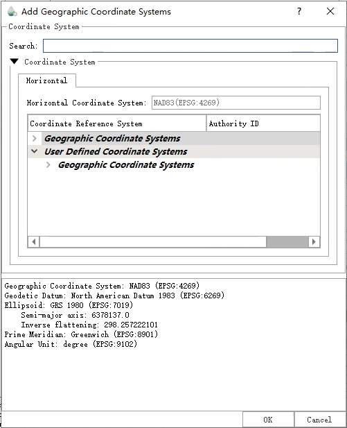
- Geographic Coordinate System: User can click Modify to select a geographic coordinate system.
- Change: When the user clicks the Change button, the following dialog box will pop up to modify the geographic coordinate system. Users can filter out the desired coordinate system through the Filter operation. Supports selection of default geographic coordinate system and custom geographic coordinate system.
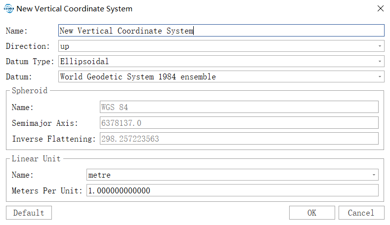
Add Vertical Coordinate System

- Name: Users can customize the name of the projection coordinate system.
- Direction: Set the direction of the coordinate axis, either upward or downward.
- Datum Type: Set the datum type of the vertical coordinate system. "Ellipsoidal" is for ellipsoidal datum, and "Gravity-related" is for gravity field datum.
- Datum: When the datum type is set to Ellipsoidal, the ellipsoidal datum can be set through this option. Once selected, the ellipsoid parameters will be automatically filled into the ellipsoid parameter list below.
- Vertical Datum: When the datum type is set to Gravity-related, the vertical datum can be set through this option.
- Linear Unit:
- Name: Users can customize the name of the linear unit or select a name from the drop-down list.
- Meters per Unit: Input the number of meters per unit.
- Spheroid: Users can click to modify and select the geographic coordinate system.
- Default: Restore default parameters.
