Simple Model

Note: When using the Tower Model Tool, the corresponding tower file (*. LiTower) must be loaded first.
Draw Simple Tower Model
Build a simple tower model. The functional interface is shown in the following figure. Click![]() to open the simple tower model file. Click
to open the simple tower model file. Click![]() to save the simple tower model file.
to save the simple tower model file.
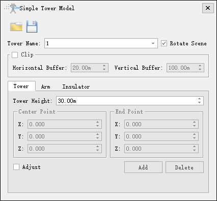
- Tower Name: Select the corresponding tower name.
- Rotate Scene: Uncheck, rotate horizontally; Check, 3D rotation.
- Clip(uncheck by default): If checked, the scene data will be clip based on the size of the buffer zone, with the tower point as the center, for easy operation; If unchecked, no clipping will be performed.
- Horizontal Buffer: Set the horizontal display range.
- Vertical Buffer: Set the vertical display range.
- Tower: Draw the tower body.
- Tower Height: Set the height of the tower.
- Center Point: Set the center point position.
- End Point: Set the position of the end point in the main direction of the tower.
- Adjust: After checking, existing model parameters can be adjusted, including height, center point, and end point.
- Add: Click to add the main body of the tower.
- Delete: Click to delete the current model and delete its related cross arms and insulators.
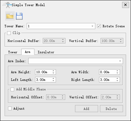
- Arm: Draw the cross arm of the tower.
- Arm Index: Cross arm number, automatically generated after clicking add.
- Arm Height: Set the height of the cross arm relative to the lowest point of the tower body.
- Arm Width: Set the width of the cross arm, which only exists for tension towers.
- Left Length: Set the left length.
- Right Length: Set the right length.
- Add Middle Phase: After checking, you can set the middle phase parameters of the cross arm.
- Horizontal Offset: Set the horizontal offset value of the middle phase (negative value on the left and positive value on the right, distinguished by minor to major towers).
- Vertical Offset: Set the vertical offset of the middle phase.
- Adjust: After checking, the cross arm model with the current number can be adjusted.
- Add: Click to add the cross arm model.
- Delete: Click to delete the cross arm model with the current number and link to delete its related insulators.
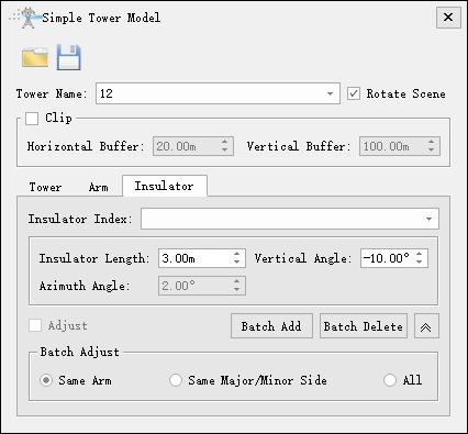
- Insulator: Draw insulators.
- Insulator Index: Insulator number, automatically added.
- Insulator Length: Set the length of the insulator.
- Vertical Angle: Set the insulator angle, which only exists for tension towers.
- Azimuth Angle: Set the azimuth angle and only add the middle phase to this parameter.
- Adjust: After checking, you can adjust the parameters of the insulator with the current number.
- Batch Add: Batch add insulators.
- Batch Delete: Batch delete insulators.
- Batch Adjust: Batch adjust insulators.
- Same Arm: Adjust the selected insulator to correspond to the insulator under the cross arm.
- Same Major/Minor Side: Adjust the selected insulators to correspond to the same side of the tower with the same size.
- All: Adjust all insulators.
Place
Place the simple tower model at the designated tower name location.

- Simple Tower Model File: Set the file path for similar simple tower models.
- Tower Name: Set the name of the tower to be placed.
Note: Ensure that both towers are both tension towers or straight line towers.
Single
Suspend a single wire for the current simple tower model.
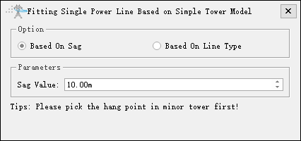
- Base On Sag: Hang the wire according to the sag value.
- Sag Value: Set the sag value.
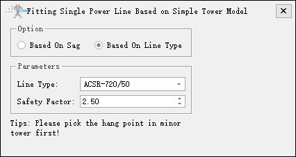
- Base On Line Type: Suspend wires based on wire type and safety factor.
- Line Type: Select the current wire type and use the built-in wire type library.
- Safety Factor: Set a safety factor, generally not less than 2.5.
- Click the left mouse button to select the suspension point for the insulator of the small tower.
- When the number of insulator layers and the number of hanging points on each layer of the small and large towers are consistent, the hanging points on the large tower can be automatically matched.
- Matching successful, wire hanging completed. If it fails, you need to click the left mouse button to select the insulator hanging point corresponding to the large tower.
- The drawing is completed.
Note: There is a difference between the entry and exit points for tension towers. The starting hanging point needs to select the outgoing tower point, and the ending hanging point needs to select the incoming tower point.
Batch
Batch suspension of wires for the current simple tower model.
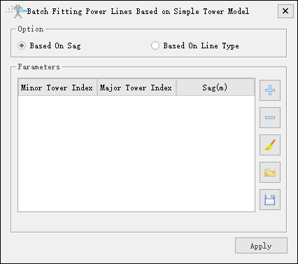
Base On Sag: Click
 to add individual segment data (set small and large tower numbers and sag values). Click
 to remove the selected segment. Click
 to clear the data list. Click
 to open the sag file. Click
 to save the sag file.
Sag File: Set the sag file path in *. csv format, recording the tower number and wire sag value for each level. The file is divided into three columns, separated by "," with the first column representing the starting tower number; The second column represents the end tower number; The third column represents the sag value. The following is an example of the sag file section:
Starting tower number, ending tower number, sag
28,29,2.5
29,30,4.0
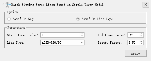
- Base On Line Type:
- Start Tower Index: Set the starting tower number.
- End Tower Index: Set the end tower number.
- Line Type: Select the current wire type and use the built-in wire type library.
- Safety Factor: Set a safety factor, generally not less than 2.5.