Strip Alignment
Brief: In the Strip Alignment module, airborne LiDAR point clouds of overlapping strips can be aligned through boresight calibration. This module includes the following functions: loading/deleting/splitting trajectories, cutting point cloud according to trajectories, matching trajectory and point cloud, transforming point cloud based on boresight calibration parameters, eliminating point cloud redundancy (cut overlap), etc.
Usage
- Open strip alignment module. Click Menu > Strip Alignment > Strip Alignment, and the corresponding interface is shown as follows.
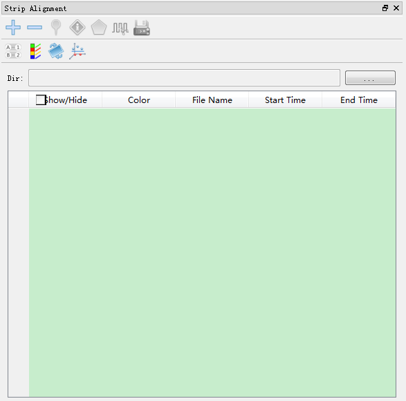
 Add Trajectories: After clicking this button, an interface pops up to ask you to set the work directory.
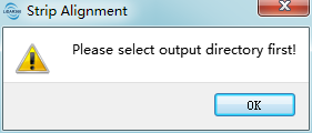
Set the directory and a dialog for adding trajectories will be shown as follows.
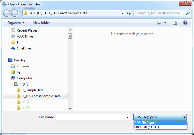
LiPowerline supports two formats of trajectory files: POS(*.pos) (text format file) and SBET(*.out)] (binary format file).
○ POS File Example 1: If the POS file does not contain GridX and GridY information, the user has to specify following headers (GPS time, longitude, latitude, height, roll angle, pitch angle and yaw angle) for data columns. An example is shown as follows.
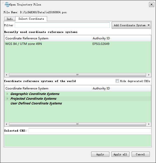
It is required to select the correct projection coordinate system as the following picture.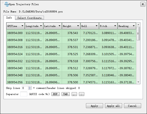
○ POS File Example 2: If the POS file contains GridX and GridY information, the user has to specify following headers (GPS time, longitude, latitude, height, roll angle, pitch angle, yaw angle, GridX and GridY) for data columns. An example is shown as follows.
If the information of GridX or GridY is not correct, the POS File Example 1 can be used.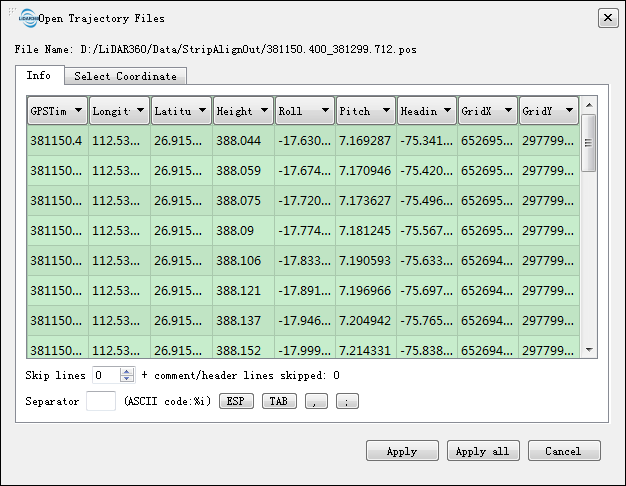
For both of the two examples, click "Apply" to make the current settings apply on current trajectory file, and all the trajectory files will be affected by the current settings if you click "Apply all".
 Delete Trajectories:
- 3.1 Select the trajectories to be deleted in the trajectory list.
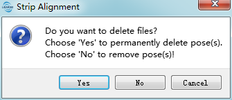
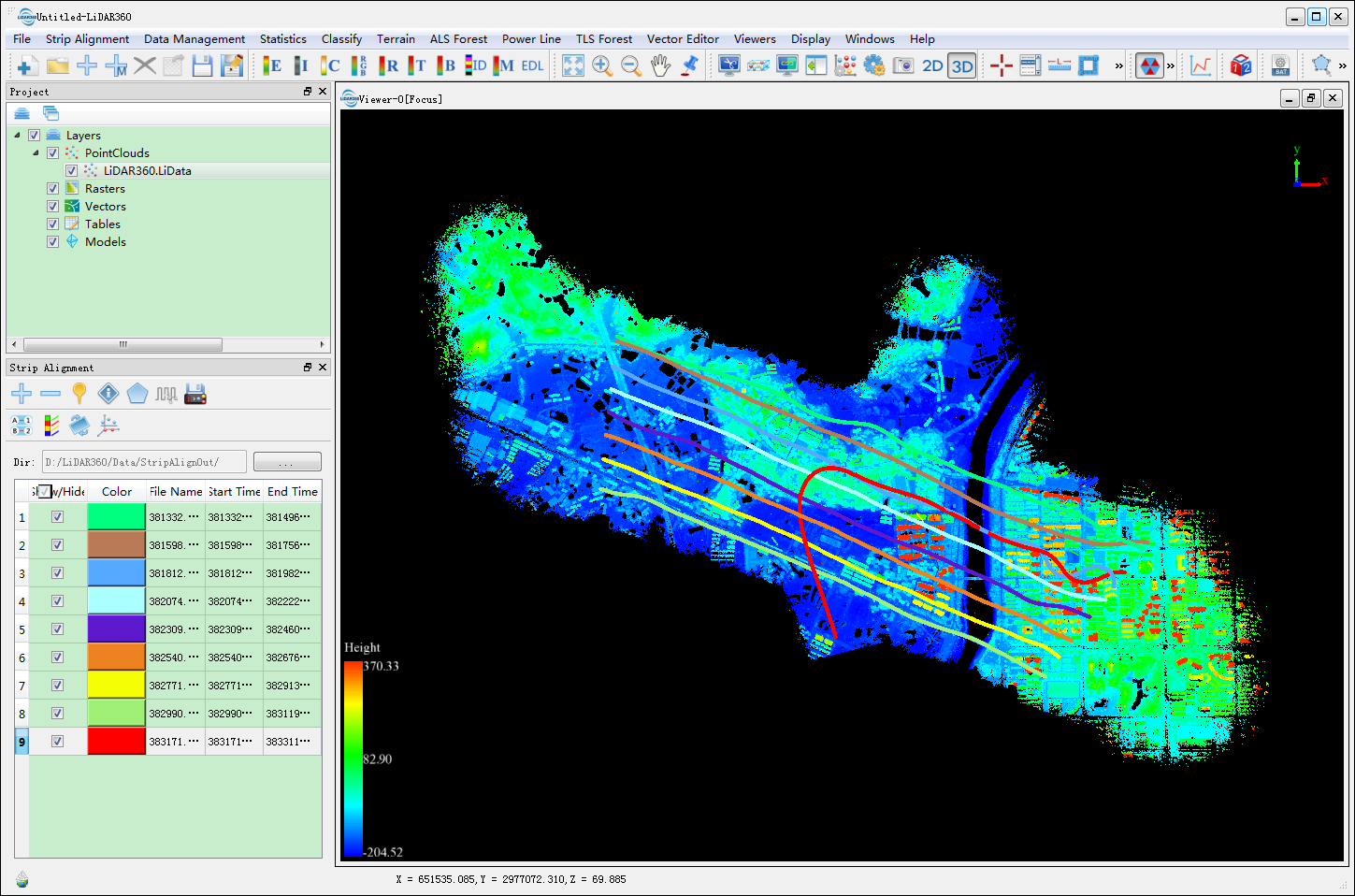
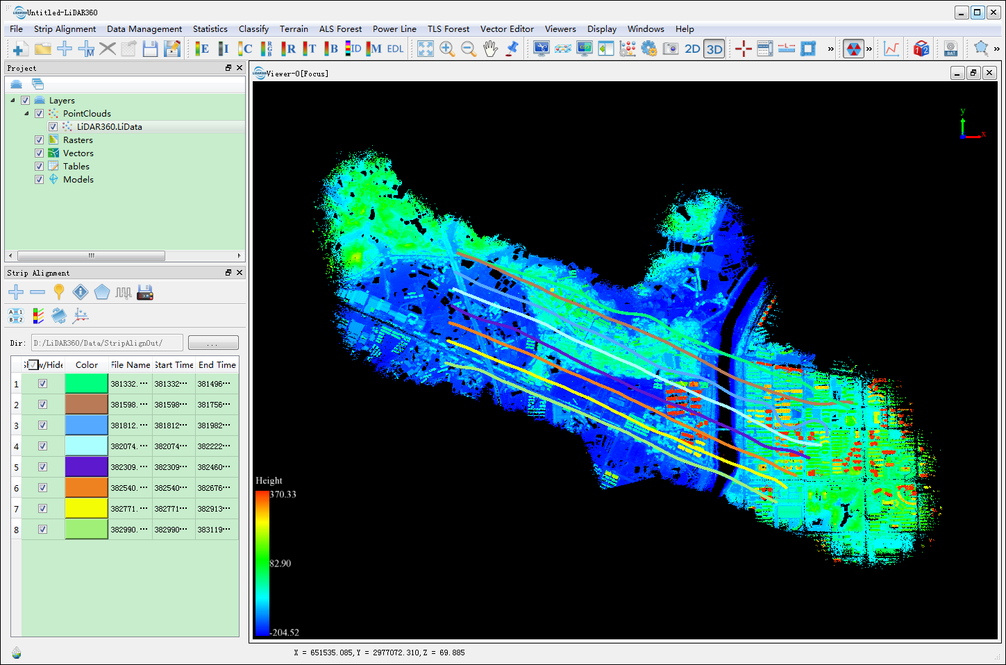
- 3.2 Click "Yes" or "No". Current selected trajectories will be removed. While clicking "Yes", the corresponding trajectory files will be deleted. The figure below demonstrates the effect of the scenes before and after the deletion of the red trajectory.
 Before Deletion
 After Deletion
- 3.1 Select the trajectories to be deleted in the trajectory list.
 Show Single Trajectory: The color of the selected trajectory will be changed gradually, and then the trajectory will twinkle several times.
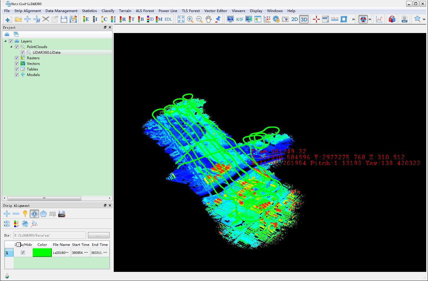
  Pick Point: Left click a certain point in the trajectory and the information of this point will be displayed.
 Draw Polygon:
 - 6.1 Click the Draw Polygon button to activate this function (Click again if you want to deactivate it).
- 6.2 Choose the vertexes of the polygon one by one by left click.
- 6.3 Delete added vertices in reverse order by right click, if some of them are unwanted.
6.4 Left double click to add the last vertex. The polygon will be stored in the "polygon.gv" file under the work directory. If this file exists, the polygon will be automatically loaded at the step 2.
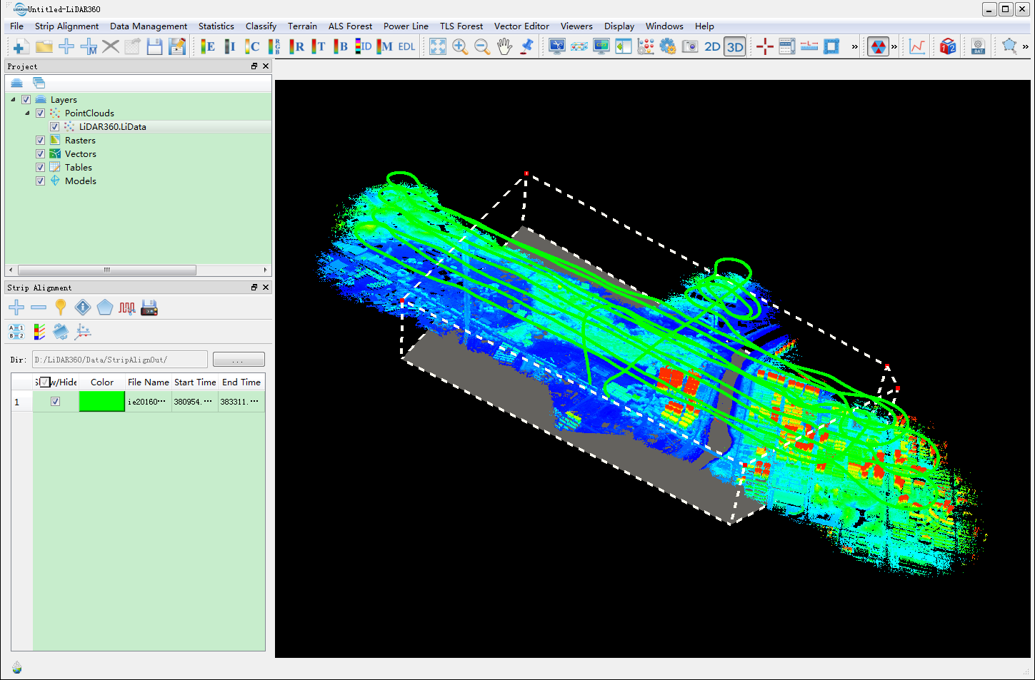
- 6.5 The polygon can be modified using left mouse button to select and drag.
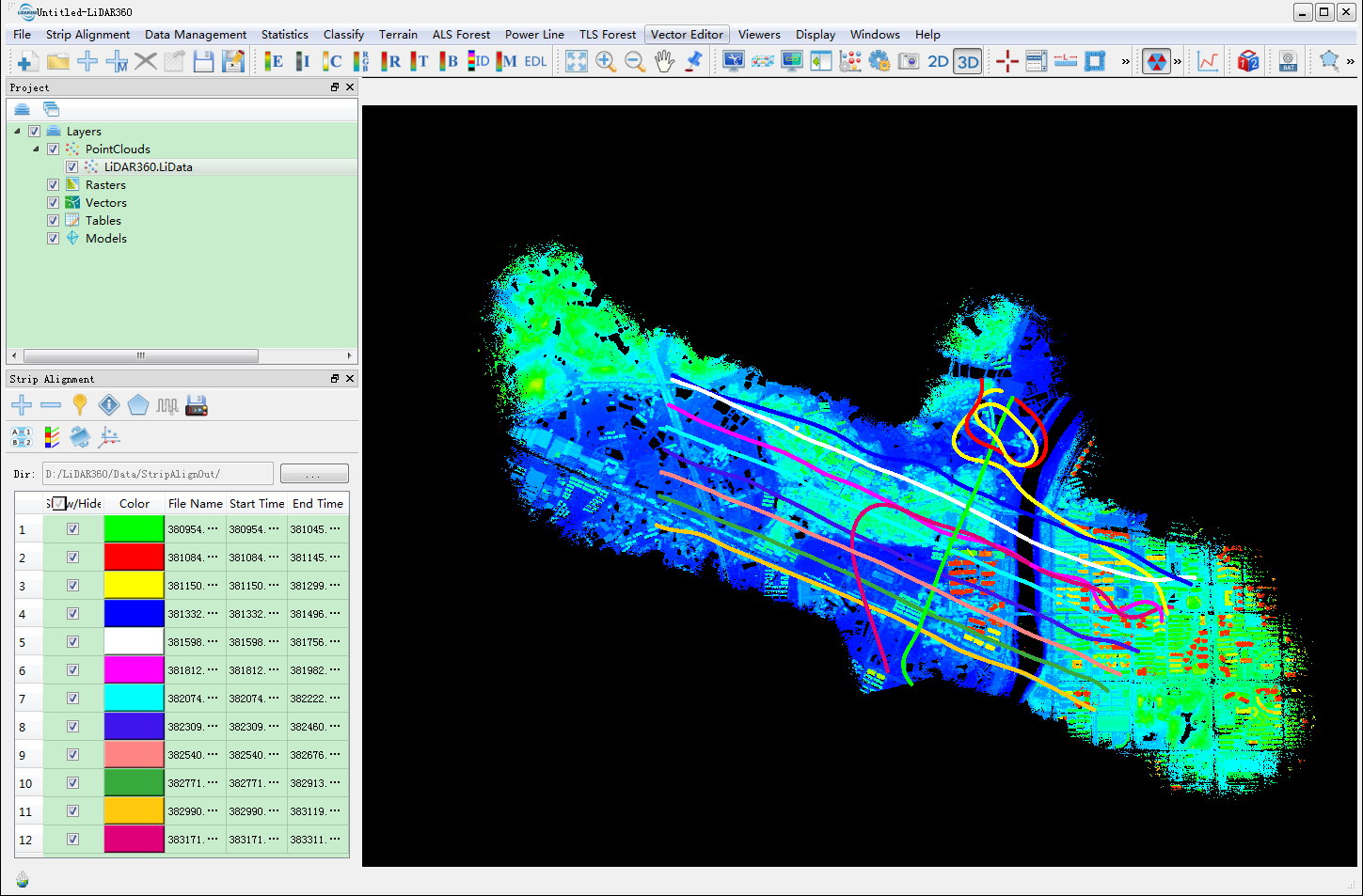
 Split Trajectories: Click this button to split the source trajectories by polygon. New generated trajectories will be stored as POS file format in the work directory and named by the GPS starting and ending times of the trajectory. An example of new file name is "GPSStartTime_GPSEndTime.POS". The effect of cutting is shown as follows. After this procedure, step 3 can be used to delete undesired trajectories.
 Cut Point Cloud Based on Trajectories.
- 8.1 Click the button to pop up a dialog.
Select the point cloud data files to be cut. Check the "Cut by Trajectories Buffer" and set the Buffer parameter as desired.
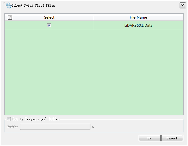
- 8.2 Click "OK". LiPowerline will cut the point cloud by the trajectories and show the process speed accordingly. The cutting results will be saved and the name of the point cloud is identical to the corresponding POS file. A dialog pops up to ask the user whether to load the results or not.
- 8.1 Click the button to pop up a dialog.
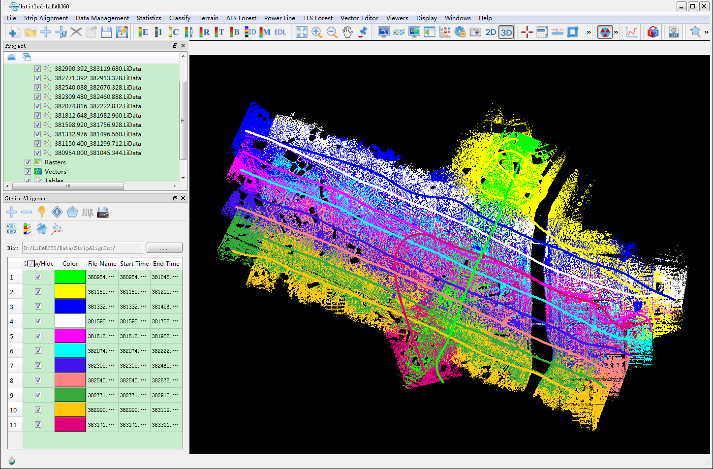
 Match Point Cloud and Trajectory: Click this button, the point cloud data and the corresponding trajectory will be displayed in the same color.
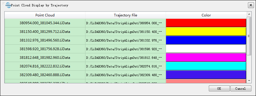
 Display Point Cloud by Trajectory: Click the button to pop up a dialog that lists the point cloud files and the corresponding trajectories. Choose an appropriate color for each trajectory to display.
 Transform: Click this button to pop up a dialog.
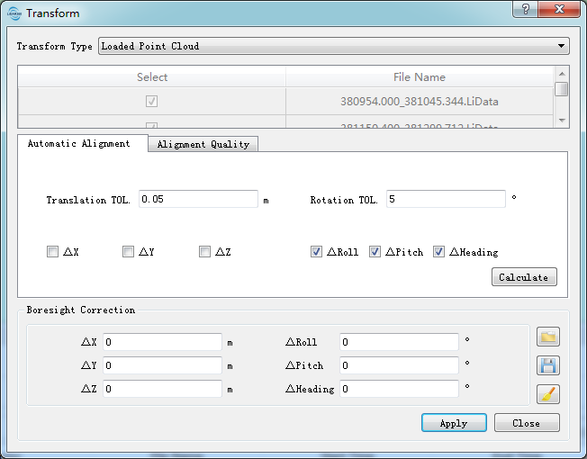
○ 11.1 This function is applied to correct the Boresight Error, which can be calculated automatically (Automatic Alignment) or input manually (Manual Alignment).
Automatic Alignment:Select the boresight error you want to correct, and set the Translation TOL and Rotation TOL. Click "Calculate" to generate the boresight error automatically and the result will be shown in the "Boresight Correction" part of the interface. After the calculation of automatic alignment, LiPowerline will figure out the Alignment Quality. The Alignment Quality will be shown in the "Alignment Quality" tab page. (Theory of correction based on automatic adjustment.)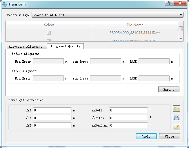 Manual Alignment:Adjust the boresight error manually. (Theory of correction based on manual measurement.) Click "Apply" and the transformation of error correction will be applied on the selected Transform Type. ○ 11.2 For both automatic and manual method, correction result can be checked in the profile window.
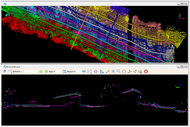 Before transformation
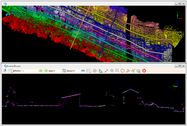 After transformation
○ 11.3 Buttons on the right of the "Boresight correction" provide the following operations: "loading from file", "saving to a file" and "cleaning".
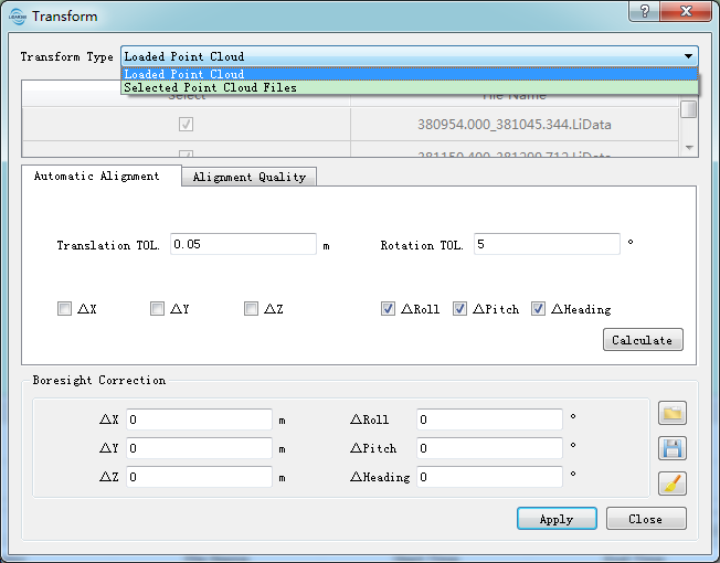
○ 11.4 If the alignment effect is satisfied, you can switch Transform Type from the "Loaded Point Cloud" to "Selected Point Cloud Files". Click "Apply" to finish the transformation.
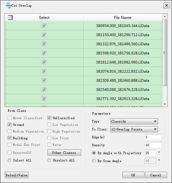
 Cut Overlap: Click this button to set the cut overlap parameters. Click "OK" button, then the redundant points between the overlapped trajectories will be classified or deleted.
Settings
- Parameters of Cutting point cloud based on Trajectories
- Buffer: The remaining distance in both sides of trajectory while cutting.
- Parameters of Transform
- Boresight Error
- ΔX/ΔY/ΔZ: Correction parameters of boresight offset error.
- ΔRoll/ΔPitch/ΔHeading: Correction parameters of boresight pose error.
- Automatic Alignment: It matches corresponding points between strips automatically and calculates optimal correction value of boresight error via adjustment.
- Translation TOL: The maximum translation tolerance of ΔX, ΔY, ΔZ. The default value is 0.05 m.
- Rotation TOL: The maximum rotation tolerance of ΔRoll, ΔPitch, ΔHeading. The default value is 5°.
- Options: Users can decide whether the 3 translations and 3 rotations are involved in adjustment to calculate correction values. For most aerial data, it is not recommended to correct ΔZ. In default state, all the rotations are selected while all the translations are unselected.
- Alignment Quality: After automatic alignment calculation, LiPowerline will figure out the alignment quality and show the result in the alignment quality result tab.
- Min Error: Minimum error of matched corresponding points.
- Max Error: Maximum error of matched corresponding points.
- RMSE: RSE error of matched corresponding points.
- Transform Type:
- Loaded Point Cloud: The loaded point cloud which is matched with trajectory in LiPowerline. When the transformation is applied, the corresponding point cloud is modified and the transformation effect can be shown in real-time. When strip alignment module exits, relevant transformation is eliminated without saving.
- Selected Point Cloud Files: In this type, the file list area on the interface will be activated, users can choose which point cloud file(s) will participate in the transformation. Then the results will be saved to the file. It doesn't loss the information even though the strip alignment module exits.
- Parameters of Cut Overlap:
- Type:
- Classify: Classify points into target category and save the result in the original point cloud file.
- Delete: Classify points into target category and then delete them from initial point cloud data (Note: If the input point cloud contains points of target category, they will also be removed).
- From Class: Point cloud target category.
- Edge: Grid unit size (length) of overlapping area. This parameter is used to rasterize the point cloud data of the overlapped area.
- Density: Smallest point density of grid unit. If the point density is smaller than the defined threshold, these points will not be classified to redundant points.
- By Angle with Trajectory: Angle between point cloud and trajectory. If this angle is larger than the threshold, the point cloud will be classified to redundant points.
- By Scan Angle: If scanning angle is larger than the threshold, point cloud will be classified to redundant points. (Note: this function can only be used when scanning angle is recorded by point cloud.)
- Type:
Note:1. The matching principle of a point cloud file and a trajectory is that: Each GPS time of all the points in the point cloud is inside the trajectory's GPS time span.2.In most cases, the effect from X,Y or Z is tiny, while the ground control points are needed for higher precision of Z value. Therefore, only Roll, Pitch and Heading are selected to take apart in the adjusting by default.3. The result may not satisfy if accuracy of the POS data file is not enough, and users can make an manual alignment based on the result.4. For Overlapped function, at least two pairs of matched point cloud and trajectories are needed.