Settings
Summary
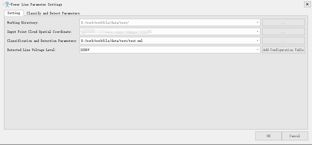
Power line parameter settings include common settings and detection parameter settings. Common settings include working directory, input point cloud spatial coordinate, classification and detection parameters, detected line voltage level; classify detection parameter settings include class settings, detection types, and safety distance settings.
Common Settings
The user can set the working directory, input point cloud spatial coordinate, classification and detection parameters, detected line voltage level and add configuration tables. The software can record the user's last 5 input history records. User can select the most recently used item in the drop-down list. The working directory is used to manage the project. The prj.ini file in the working directory records the point cloud coordinate system, classes and detection parameters, and voltage level of the current project.

- Working Directory: Used to save the intermediate and final results.
- Input Point Cloud Spatial Coordinate: The coordinate system of the point cloud data.
- Classification and Detection Parameters: Set the path of the xml format configuration file.
- Detected Line Voltage Level: The voltage level of the detected power line.
- Add Configuration Table: If the detection line voltage level list is empty and does not contain the current voltage level, user can add a new voltage level by adding a configuration table and set its safety distance detection parameters.
Detection Parameter Settings
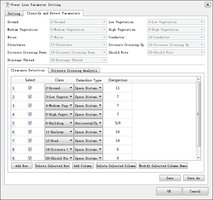
Displays key detection classes and safety distance detection parameters. User can add voltage levels and then configure their corresponding detection parameters, including clearance distance analysis and crossing analysis. Clearance detection distance analysis includes detections for different classes of objects, as well as different safety distance and distance detection methods. For scissors crossing analysis, user only needs to set the classes to be detected, and user does not need to set a safety distance.

- Select: Whether to detect this class.
- Checked (default): Detect the danger point in this class.
- Unchecked (default): Do not detect the danger point in this class.
- Class: Select the number (from 1 to 32) of the class in the drop-down menu.
- Detection Type: Select the detection type in the drop-down menu.
- Clearance Distance: Judge the point whether to be a danger point by the clearance distance. If the distance is less than this value, it is a danger point.
- Vertical Distance: Judge the point whether to be a danger point by the vertical distance. If the distance is less than this value, it is a danger point.
- Horizontal Distance: Judge the point whether to be a danger point by the horizontal distance. If the distance is less than this value, it is a danger point.
- Horizontal Distance / Vertical Distance: Firstly judge the point whether to be a danger point by the horizontal distance. If the distance is less than set horizontal value, it is a danger point. If the distance is larger than set horizontal value, judge the point whether to be a danger point by the vertical distance.
- Horizontal Distance / Clearance Distance: Firstly judge the point whether to be a danger point by the horizontal distance. If the distance is less than set horizontal value, it is a danger point. If the distance is larger than set horizontal value, judge the point whether to be a danger point by the clearance distance.
- Horizontal Distance / Vertical Distance / Clearance Distance: Firstly judge the point whether to be a danger point by the horizontal distance. If the distance is less than set horizontal value, it is a danger point. If the distance is larger than set horizontal value, judge the point whether to be a danger point by the vertical distance. If the distance is less than the set vertical distance, it is a danger point. If the distance is larger than the set vertical distance, judge the point whether to be a danger point by the clearance distance then.
- Add Row: Add a new detection class record.
- Delete Selected Row: Delete the selected row of detection class.
- Add Column: Add a new column for a severity level threshold. I.E., severe, important, and general.
- Delete Selected Column: Delete the selected column.
- Modify Selected Column Name: Modify the name of selected column.
- Save: Save the configuration to the current xml file.
- Save as: Save the configuration as a new xml file.
Note: In crossing analysis, if user does not select the detection class, software will only analyze the upper crossing and lower crossing by default.