Section Map
Summary
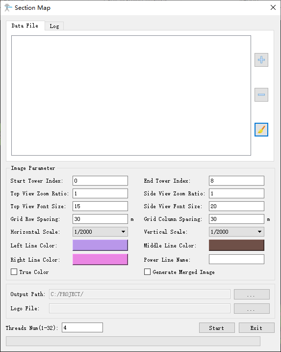
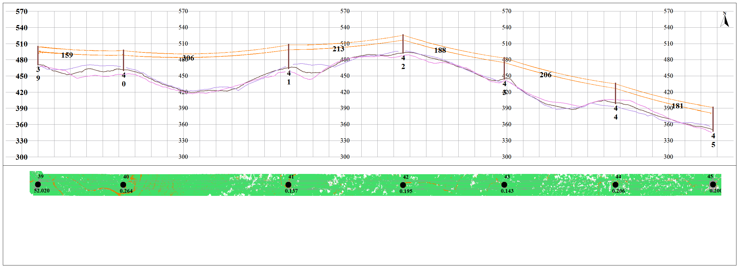
Generate the power line section map based on the point cloud data. The function interface is shown in the figure below. This function can process multiple data simultaneously. Click ![]() to add the data to be processed. Click
to add the data to be processed. Click ![]() to remove the selected data. Click
to remove the selected data. Click ![]() to clear the data list.
to clear the data list.
Usage
Click Toolbox > Result Finishing > Section Map


Settings
- Power Line Name: Set the name of transmission line. The software can record the user's current settings and automatically restore the settings when opened again.
- Start Tower Index: Towers with index numbers smaller than this value are not involved in the calculation. The default value is the minimum Index in the tower file.
- End Tower Index: Towers with index numbers larger than this value are not involved in the calculation. The default value is the maximum Index in the tower file.
- Top View Zoom Ratio (default value is "1"): Set the top view zoom ratio.
- Side View Zoom Ratio (default value is "1"): Set the side view zoom ratio.
- Top View Font Size (default value is "15"): Set the top view font size.
- Side View Font Size (default value is "20"): Set the side view font size.
- Grid Row Spacing (meters) (default value is "30"): Set the grid row spacing.
- Grid Column Spacing (meters) (default value is "30"): Set the grid column spacing.
- Horizontal Scale (default value is "1/2000"): Set the horizontal scale.
- Vertical Scale (default is "1/2000"): Set the vertical scale.
- Left Line Color: Set the color of the left line.
- Middle Line Color: Set the color of the middle line.
- Right Line Color: Set the color of the right side line.
- True Color: Whether to display in true color.
- Generate Merged Image: Whether to generate merged image.
- Output Path: Set the output path of the section maps.
- Logo File: Set the logo file path.
- Threads Number (default value is "4"): Set the number of thread (1 to 32) to run this function. The software can record the currently setting and when the user open this function again, the setting will be kept.