Trajectory Operation
Usage

Clip Tower
Clip tower is mainly to display the tower of the trajectory planning independently for easy trajectory editing.
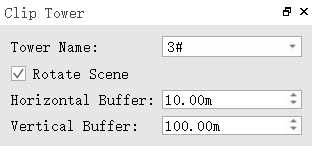
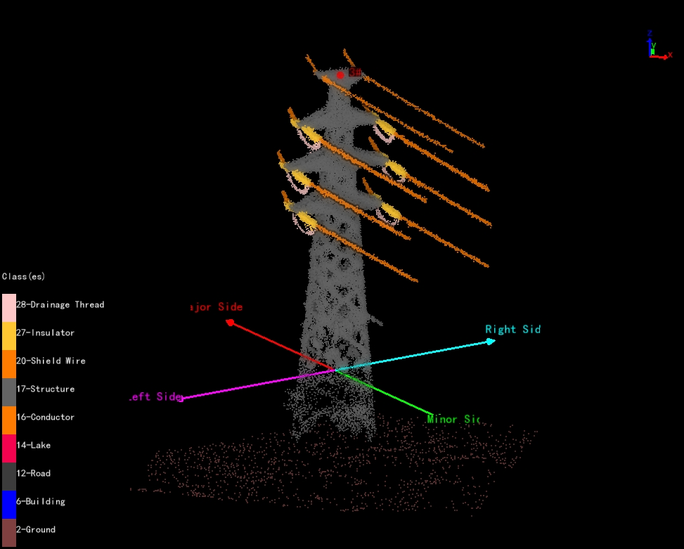
- Tower Name: Select the corresponding tower name.
- Rotate Scene: Uncheck, horizontal rotation; check, 3D rotation.
- Horizontal Buffer: Set the horizontal display range.
- Vertical Buffer: Set the vertical display range.
Mark Part Point
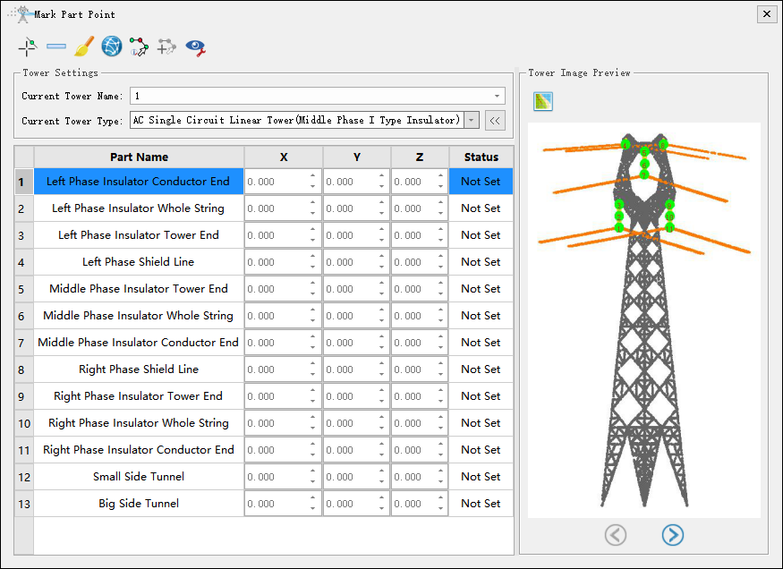
Note: Before marking part points, it is necessary to mark tower and set the tower type.
Tower Settings
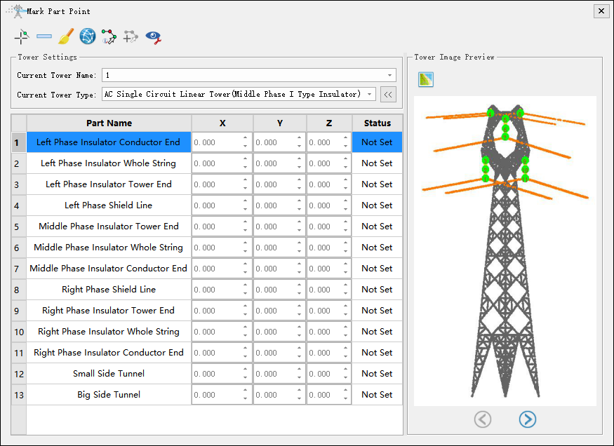
Mark Part Point
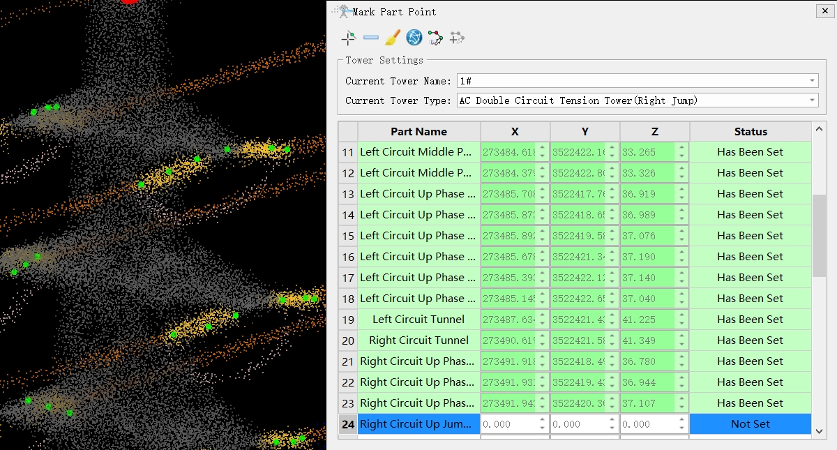
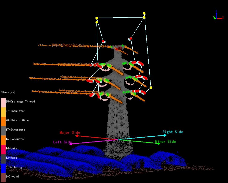
After selecting the tower type, there will be a corresponding list of part point. Select the corresponding part point on the point cloud according to the order of the list. The status of marked part point is "Has Been Set", and the status of unmarked part point is "Not Set". If there are part point that do not need to be marked, you can skip them directly and select the following part point for marking. After marking all part point, click the marking button again to finish the marking function. The list of part point and the results of part point marking are shown in the following figure.
Delete Part Point
Select the part point in the list and click the button to delete the part point.
Clear
Click the button to clear all marked part point.
Channel Perspective
Click the button to display the tower from the perspective of the channel.
Automatic Waypoint Generation
After clicking the button, corresponding waypoints will be automatically generated when generating part point.
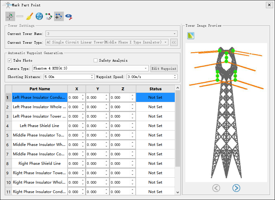
- Take Photo(Checked by default): If checked, the waypoint will include photo information.
- Safety Analysis(Unchecked by default): If checked, the safety of the trajectory will be analyzed.
- Camera Type: Set current camera type. The current camera type is set by default through Project Configuration->Camera Settings.
- Edit Waypoint: Switch to edit waypoint function.
- Shooting Distance(m, default value is "5.0"): Set the distance from the waypoint to the part point.
- Waypoint Speed(m/s, default value is "3.0"): Set the waypoint speed.
Hide XYZ Columns
If checked, hide the XYZ columns of the table; If uncheck, display the XYZ columns of the table.
Tower Image Preview
Generate Image
Generate tower preview images based on tower point cloud and "Has Been Set" part point.
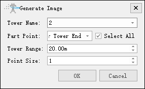
- Tower Name: Select the current tower name.
- Part Point: Check the part points that need to generate image information.
- Select All: Check or uncheck all part points.
- Tower Range(m, default value is "20.0"): Set the extraction point cloud range for the current tower. By adjusting the range, fully display the tower and part points.
- Point Size(default value is "1"): Set the size of a single point in the point cloud in the image.
Automatic Generation
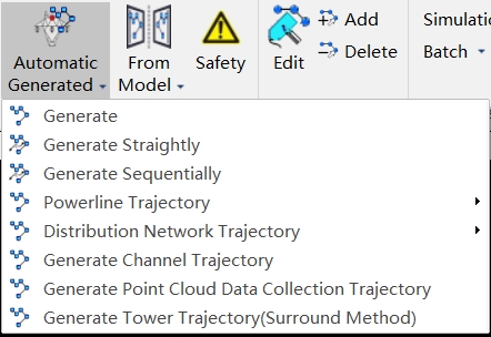
Automatic generation is to generate trajectory according to the inspection configuration. The drop-down menu also includes functions such as "Generate", "Generate Straightly", "Generate Sequentially", "Powerline Trajectory", "Distribution Network Trajectory", "Generate Channel Trajectory", "Generate Point Cloud Data Collection Trajectory", "Generate Tower Trajectory(Surround Method)", etc.
Automatic Generated
Automatically generate refined inspection trajectory for towers based on inspection configuration. After clicking the button, set the camera type and waypoint speed, and click "Apply" to automatically generate the trajectory.

- Camera Type: Select camera type for taking photos. Add a new camera type in the camera configuration.
- Waypoint Speed(m, default value is "3.0"): Set waypoint speed.
Generate
Automatically generated based on inspection configuration and shortest path principle.
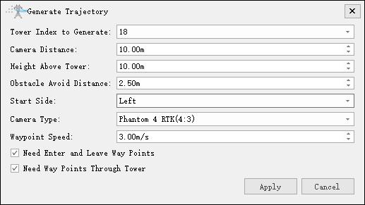
- Tower Index to Generate: The tower index needs to generate the trajectory.
- Camera Distance(m, default value is "10"): The shooting distance from the waypoint to the part point.
- Height Above Tower(m, default value is "10"): Height above tower.
- Obstacle Avoid Distance(m, default value is "2.5"): Distance for obstacle avoidance detection.
- Start Side(default value is "Left"): Waypoint shooting starting side.
- Camera Type: Select camera type for taking photos. Add a new camera type in the camera configuration.
- Waypoint Speed(m/s, default value is "3.0"): Set waypoint speed.
- Need Enter and Leave Way Points(Checked by default): Add two auxiliary points for exiting the tower and entering the tower.
- Need Way Points Through Tower(Checked by default): Add auxiliary points for passing the tower.
Generate Straightly
Generate flight trajectories directly by connecting parts points in order. There may be a possibility of the trajectory passing through the tower, and auxiliary waypoints need to be manually added.
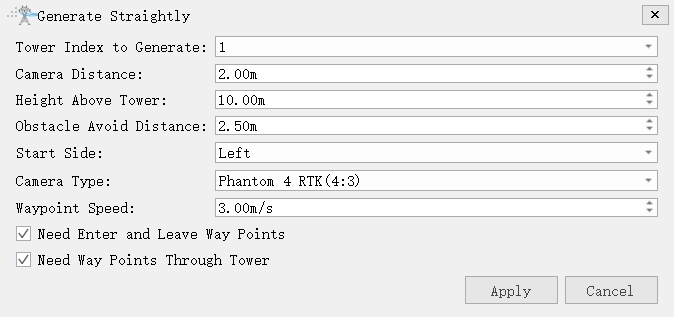
- Tower Index to Generate: The tower index needs to generate the trajectory.
- Camera Distance(m, default value is "10"): The shooting distance from the waypoint to the part point.
- Height Above Tower(m, default value is "10"): Height above tower.
- Obstacle Avoid Distance(m, default value is "2.5"): Distance for obstacle avoidance detection.
- Start Side(default is "Left"): Waypoint shooting starting side.
- Camera Type: Select camera type for taking photos. Add a new camera type in the camera configuration.
- Waypoint Speed(m/s, default value is "3.0"): Set waypoint speed.
- Need Enter and Leave Way Points(Checked by default): Add two auxiliary points for exiting the tower and entering the tower.
- Need Way Points Through Tower(Checked by default): Add auxiliary points for passing the tower.
Generate Sequentially
Automatically generate trajectory based on inspection configuration and part point order.
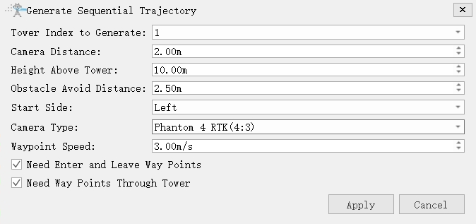
- Tower Index to Generate: The tower index needs to generate the trajectory.
- Camera Distance(m, default value is "10"): The shooting distance from the waypoint to the part point.
- Height Above Tower(m, default value is "10"): Height above tower.
- Obstacle Avoid Distance(m, default value is "2.5"): Distance for obstacle avoidance detection.
- Start Side(default is "Left"): Waypoint shooting starting side.
- Camera Type: Select camera type for taking photos. Add a new camera type in the camera configuration.
- Waypoint Speed(m/s, default value is "3.0"): Set waypoint speed.
- Need Enter and Leave Way Points(Checked by default): Add two auxiliary points for exiting the tower and entering the tower.
- Need Way Points Through Tower(Checked by default): Add auxiliary points for passing the tower.
Batch Power Line Trajectory Generating
Batch generation of power line inspection trajectory(Add point cloud data or vector data to generate trajectory in batches).
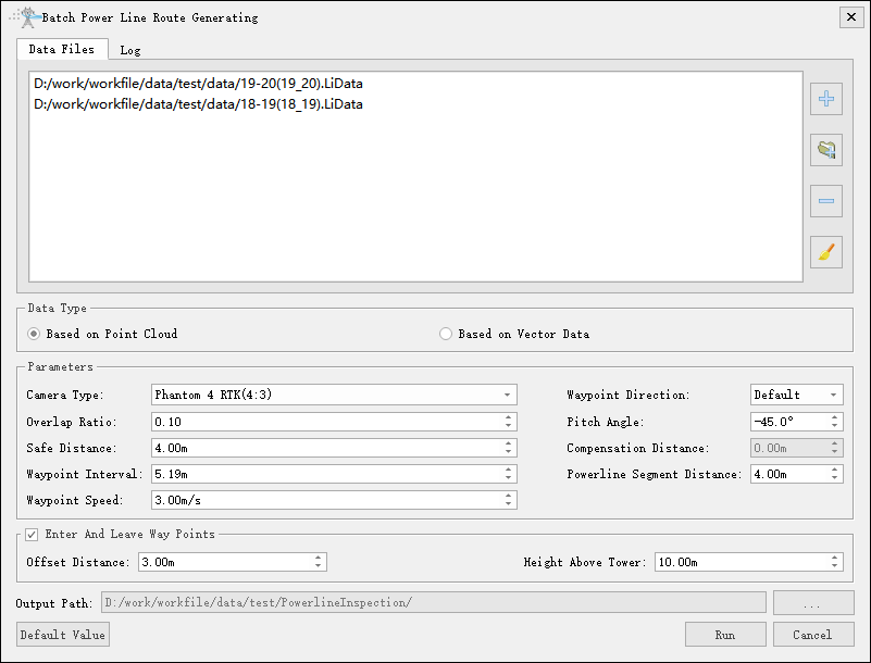
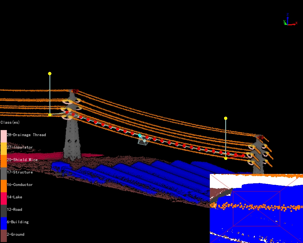
- Data Type:
- Based on Point Cloud: Generating trajectory based on point cloud.
- Based on Vector Data: Generating trajectory based on vector data.
- Parameters:
- Camera Type: Select camera type for taking photos. Add a new camera type in the camera configuration.
- Waypoint Direction: Set the position of the waypoint relative to the power line. When selecting "Default", the waypoint of the left phase is on the left side of power line, and the waypoint of the right phase is on the right side of power line. When selecting "Left Side" or "Right Side", the waypoint is located on the left and right sides of the power line.
- Overlap Ratio(default value is "0.1"): Set the overlap ratio of adjacent photos.
- Pitch Angle(-90~0)(°, default value is "-45.0"): Set the depression angle of the shooting waypoint.
- Safe Distance(m, default value is "4.0"): Set safe distance and power line obstacle avoidance detection.
- Compensation Distance(m, default value is "0.0"): Set compensation distance. The vector line is located at the bottom of the power line point data. Used to compensate for the distance between vector lines and point clouds.Only used for vector data.
- Waypoint Interval(m, default value is "0.5"): Set the distance between the waypoints and perform the safety inspection between the waypoints. Automatically calculate the Waypoint interval when setting the overlap ratio.
- Powerline Segment Distance(m, default value is "4.0"): Set the clustering threshold and cluster the point cloud points.Only used for point cloud data.
- Waypoint Speed(m/s, default value is "3.0"): Set waypoint speed.
- Enter And Leave Way Points: Add two auxiliary points for entering the tower and leaving the tower.
- Offset Distance(m, default value is "3.0"): Set horizontal offset distance.
- Height Above Tower(m, default value is "10.0"): Set height above tower.
- Output Path: Set the output path of the trajectory.
- Default Value: Click "Default Value" to restore the initial parameters.
- Run: Click "Run" to start the calculation.
Merge/Split Trajectory Files
Merge and split shield line and power line trajectory.
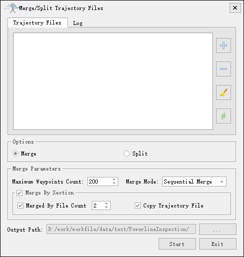
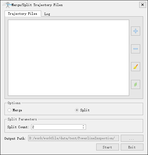
- Option: Check the "Merge" and "Split" options.
- Merge Parameters: Customize the maximum count of waypoints based on the maximum waypoints supported by the UAV. The merge mode supports two types: sequential merge and interval reverse merge. The merging function by section supports merging by the number of files. For example, if set to 2, two trajectories can be merged, and the waypoint count of merged trajectory cannot exceed the maximum count. If it exceeds, the merge will be abandoned. If "Copy Trajectory File" is checked, copy and output trajectory that do not meet the merging requirements.
- Split Parameters: Default 2, customizable.
- Output Path: Specify the path to save the file results.
Generate Distribution Network Trajectory
Generate inspection trajectory suitable for distribution networks (Distribution network trajectory mode are divided into mode 1, mode 2 and mode 3 and mode 4. The four different modes generate distribution network trajectory).
Mode 1
Generate 3 photo waypoints for each tower based on the tower marking points.
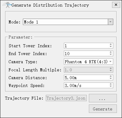
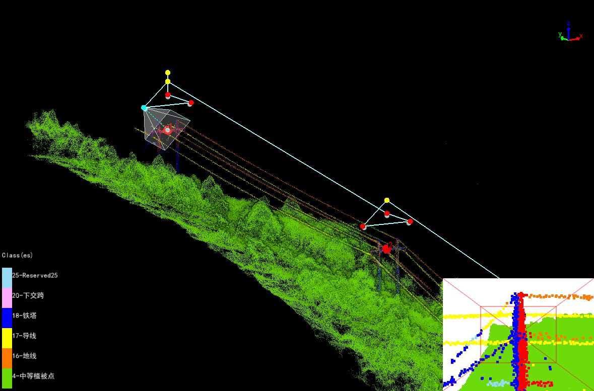
- Mode(default is "Mode 1"): Three photos of a single tower (from the left, right, and top of the tower).
- Start Tower Index: Set the starting tower index.
- End Tower Index: Set end tower index.
- Camera Type: Select camera type for taking photos. Add a new camera type in the camera configuration.
- Focal Length Multiple: Set camera focal length.
- Waypoint Speed(m/s, default value is "3.0"): Set waypoint speed.
- Camera Distance(m, default value is "8.0"): The shooting distance from the waypoint to the part point.
Mode 2
Take 13 photos of each tower on the trajectory, including the tower marking point, tower base, and major side channel.
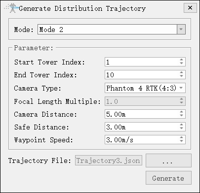
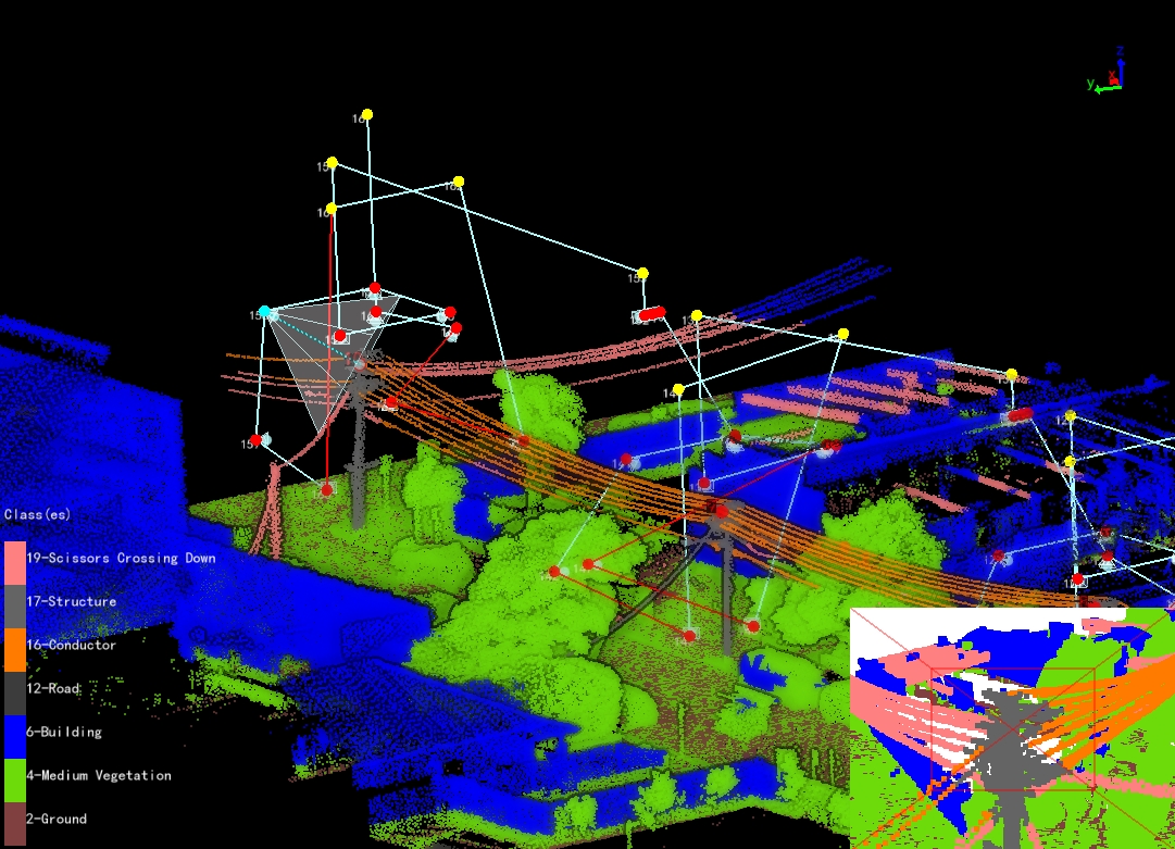
- Mode 2: Thirteen photos of a single tower. (Eight photos taken from the four directions of the tower at two heights, two photos taken from the tower base, and three photos taken from the major side.)
- Safe Distance(m, default value is "3.0"): Set safe distance and conduct obstacle avoidance detection.
Note: To avoid collisions with towers during UAV return, the automatically generated trajectory needs to check if the starting point is higher than the tower. After generating the trajectory, it is recommended to analyze the safety.
Mode 3
Take 6 photos of each tower on the trajectory, including tower marking point, tower body, and major and minor side channel.
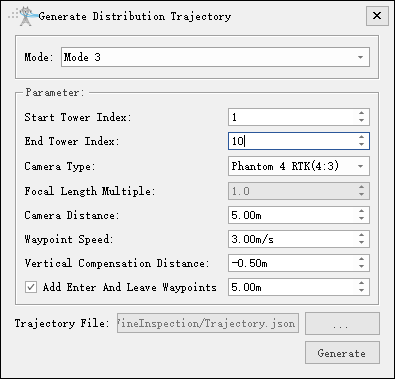
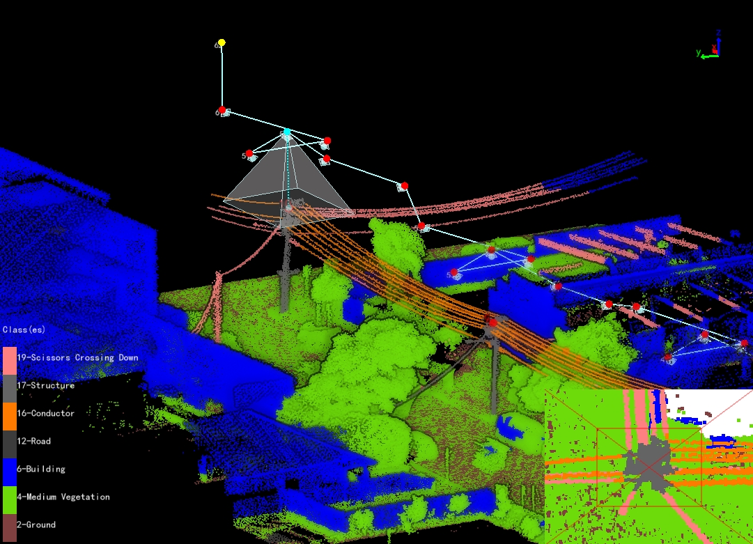
- Mode 3: Six photos of a single tower. (overall view of the tower, minor side, major side, left and right of the tower head, and top view of the tower head.)
- Vertical Compensation Distance(m, default value is "-0.5"): Adjust the height of the target points for photography on the left and right sides of the tower head. Positive value, the target point moves up. Negative value, the target point moves down.
- Enter And Leave Waypoints(check by default): Add two auxiliary points for entering and leaving the tower.
Mode 4
Take 8 photos of each tower on the trajectory, including tower head, cross arm, insulator, major and minor side channel.
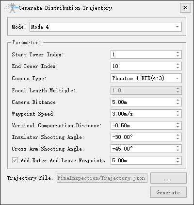
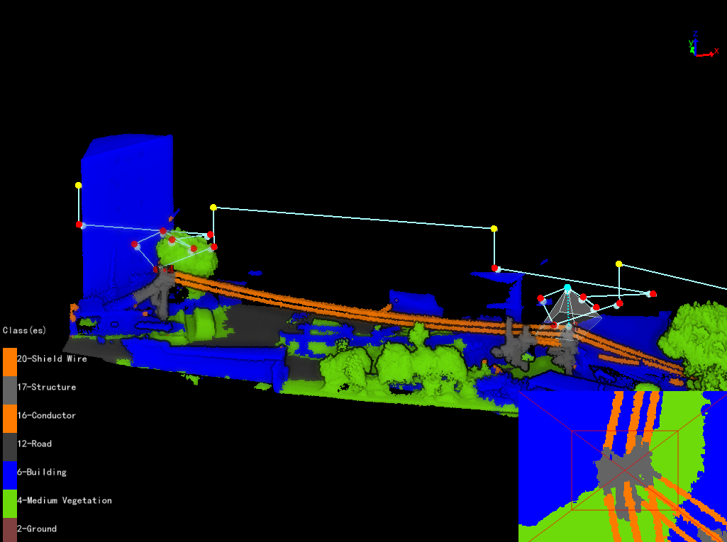
- Mode 4: Eight photos of a single tower. (overall view of the tower, cross arm, insulator, top view of the tower head, minor side and major side.)
- Insulator Shooting Angle(°, default value is "-30.0"): Set the shooting angle of the insulator.
- Cross Arm Shooting Angle(°, default value is "-45.0"): Set the shooting angle of the cross arm.
Generate Distribution Network Trajectory Model
Generate distribution network trajectory model based on the distribution network trajectory.
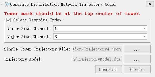
- Minor Side Channel: Select the waypoint number for minor side channel of the trajectory, and if not available, do not select it.
- Major Side Channel: Select the waypoint number for major side channel of the trajectory, and if not available, do not select it.
- Single Tower Trajectory File: Choose a single tower trajectory.
- Trajectory Model: Set the trajectory model path. The model file format is . dtm.
Generate Distribution Network Trajectory From Model
Batch generate distribution network trajectory files from models.
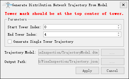
- Start Tower Index: Set the starting tower index.
- End Tower Index: Set the end tower index.
- Generate Single Tower Trajectory: If checked, generate corresponding single tower trajectory based on the starting and ending towers; If unchecked, generate a single trajectory.
- Trajectory Model: Select trajectory model file.
- Trajectory File: If "Generate Single Tower Trajectory" is checked, set distribution network trajectory folder; If "Generate Single Tower Trajectory" is unchecked, set distribution network trajectory path.
Generate Distribution Network Tower Trajectory(Surround Method)
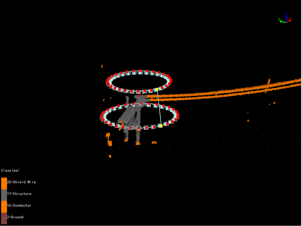
Automatically generate a circular trajectory with the tower marker point as the center. Take multi-directional and multi height photos of the tower.
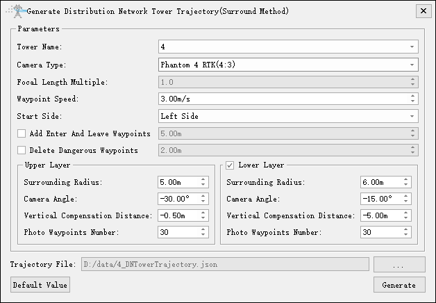
- Tower Name: Select the current tower name.
- Camera Type: Select camera type for taking photos. Add a new camera type in the camera configuration.
- Focal Length Multiple: Set camera focal length.
- Waypoint Speed(m/s, default value is "3.0"): Set waypoint speed.
- Start Side(default value is "Left Side"): Waypoint shooting starting side.
- Add Enter And Leave Waypoints: Add two auxiliary points for entering and leaving the tower.
- Delete Dangerous Waypoints: Delete dangerous waypoints based on obstacle avoidance distance and point cloud data.
- Upper Layer
- Surround Radius(m, default value is "5.0"): Horizontal distance from waypoint to tower marking point.
- Camera Angle(°, default value is "-30.0"): Pitch angle from waypoint to target point.
- Vertical Compensation Distance(m, default value is "-0.5"): Adjust the height of the target points for photography on the tower head. Positive value, the target point moves up. Negative value, the target point moves down.
- Photo Waypoint Number(default value is "30"): Generate a circular trajectory uniformly based on the "Photo Waypoint Number" in the current layer.
- Lower Layer: If checked, generate a two-layer circular trajectory.
- Surround Radius(m, default value is "6.0"): Horizontal distance from waypoint to tower marking point.
- Camera Angle(°, default value is "--15.0"): Pitch angle from waypoint to target point.
- Vertical Compensation Distance(m, default value is "-7.0"): Adjust the height of the target points for photography on the tower head. Positive value, the target point moves up. Negative value, the target point moves down.
- Photo Waypoint Number(default value is "30"): Generate a circular trajectory uniformly based on the "Photo Waypoint Number" in the current layer.
- Default Value: Click "Default Value" to restore the initial parameters.
Generate Channel Trajectory
Generate the channel inspection trajectory above the line.
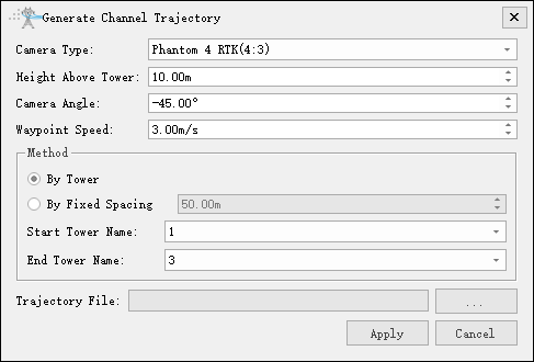
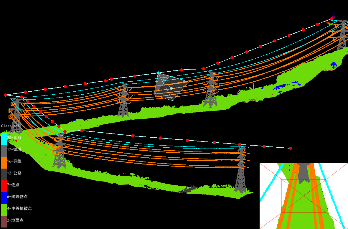
- Camera Type: Select camera type for taking photos. Add a new camera type in the camera configuration.
- Height Above Tower(m, default value is "10.0"): Distance of passage point height above tower.
- Camera Angle(°, default value is "-45.0"): Set the depression angle of the shooting waypoint.
- Waypoint Speed(m/s, default value is "3.0"): Set waypoint speed.
- By Tower: Whether to generate the channel trajectory according to the tower information.
- By Fixed Spacing(m, default value is "50.0"): Whether to generate the channel trajectory according to the fixed spacing? According to the fixed spacing, input the parameter distance at every interval to generate a trajectory.
- Start Tower Name: Set the name of the starting tower and generate a trajectory from the tower.
- End Tower Name: Set the name of the end tower and generate a trajectory to the tower.
Generate Point Cloud Data Collection Trajectory
Base on point cloud data, generate unmanned aerial vehicle (UAV) trajectory for airborne LiDAR equipment during field point cloud data collection .
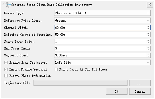
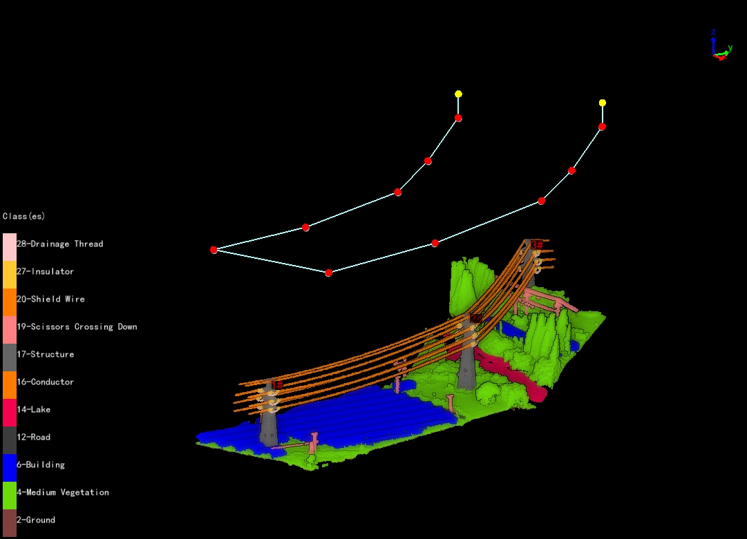
- Camera Type: Select camera type for taking photos. Add a new camera type in the camera configuration.
- Reference Point Class: Optional shield line, conductor, and ground.
- Channel width(m, default value is "60.0"): Set point cloud channel width.
- Relative Height of Waypoint(m, default value is "50.0"): The height of the waypoint relative to the reference point.
- Start Tower Index: Set the starting tower index, and generate the trajectory from the tower.
- End Tower Index: Set the the end tower index, and generate the trajectory to the tower.
- Waypoint Speed(m/s, default value is "3.0"): Set waypoint speed.
- Single Side Trajectory: If checked, you can choose the left and right sides; If unchecked, for both side trajectory.
- Insert Middle Waypoint: Add a waypoint in the middle of the tower.
- Start Point At The End Point: If checked, the starting and ending waypoints are both near the ending tower.
- Remove Photo Information: If checked, remove all camera information.
Generate Tower Trajectory(Surround Method)
Automatically generate a panoramic shooting trajectory for the tower. The waypoints are located on the front, back, left, and right sides of the tower, and the number of waypoints on each side is determined by the vertical overlap rate. Each waypoint can take multiple photos, and the number of photos is determined by the horizontal overlap rate and camera type.
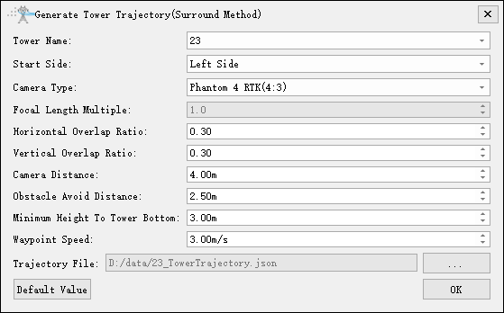
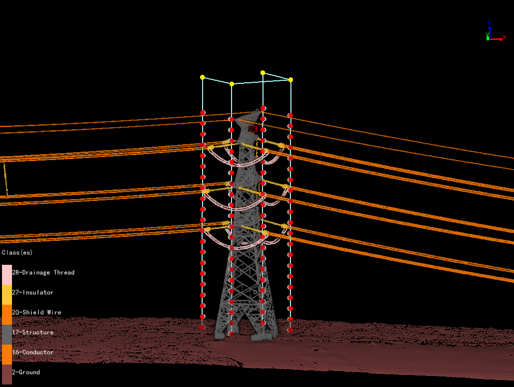
- Tower Name: Select the current tower name.
- Start Side(default value is "Left Side"): Waypoint shooting starting side.
- Camera Type: Select camera type for taking photos. Add a new camera type in the camera configuration.
- Focal Length Multiple: Set camera focal length.
- Horizontal Overlap Ratio(default value is "0.3"): Overlap rate of photos on the same side of the tower. It determines the number of photos on the current side.
- Vertical Overlap Ratio(default value is "0.3"): The overlap rate of waypoints on the same side of the tower. It determines the number of waypoints on the current side.
- Camera Distance(m, default value is "4.0"): The closest distance from the waypoint to the tower point cloud box.
- Obstacle Avoid Distance(m, default value is "2.5"): Distance for obstacle avoidance detection.
- Minimum Height To Tower Bottom(m, default value is "3.0"): Minimum height from waypoint to ground point.
- Waypoint Speed(m/s, default value is "3.0"): Set waypoint speed.
- Default Value: Click "Default Value" to restore the initial parameters.
From Model
The "Generate Trajectory By Model" function can use existing trajectory model to batch generate trajectory. Trajectory model can be obtained through the "Generate Trajectory Model" function in the drop-down menu. When there are a large number of duplicate towers on the same line, it can greatly reduce the workload of users.
Trajectory Model
Select the planned trajectory, click "Generate Trajectory Model" from the drop-down menu, and click Generate. The file name will be named according to the tower types, the file format is .tm format. The default output path is the "Fine Inspection" folder.
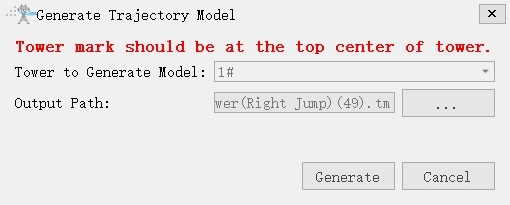
Generate Trajectory By Mode
After the trajectory model is generated, it is necessary to mark the parts of the tower. Mark all the part points according to the inspection configuration of the same tower type, and ensure that the number and location of the part points are consistent with the trajectory model.
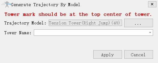
Safety
The "Safety" function can check the obstacle avoidance distance between the trajectory and point cloud data, as well as the safe distance between waypoints. If distance is greater than "Obstacle Avoidance Distance", the list will be displayed in red, and the trajectory in the point cloud will also be displayed in red. Double-click the list item to locate the corresponding trajectory, adjust it by editing the trajectory or adding auxiliary waypoints, and then refresh.
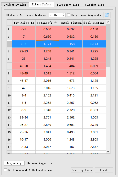
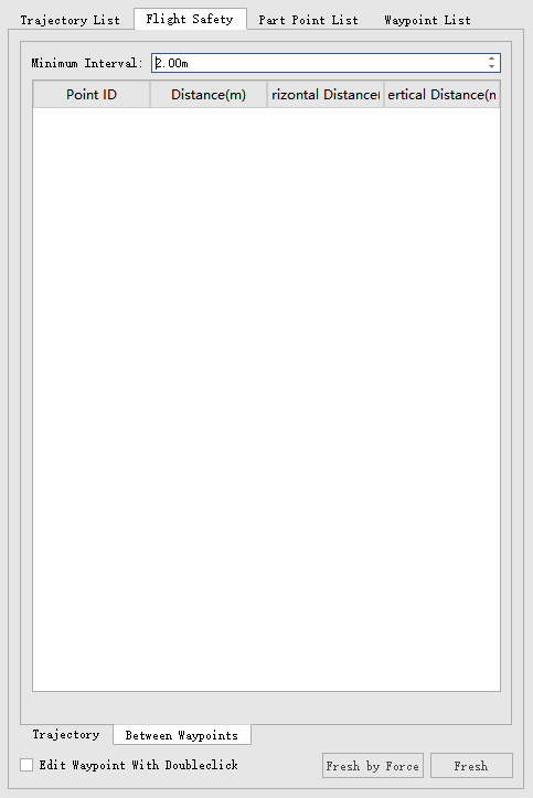
- Obstacle Avoidance Distance: The minimum distance between the trajectory and the point cloud data.
- Only Check Waypoints: If checked, only analyze the safety of the waypoint.
- Export dangerous results in the safety table: Click
 to export dangerous results.
 - Fresh by Force: Perform a forced refresh after adjusting the waypoints.
- Fresh: Refresh after adjusting the waypoint.