Exercise 2. DEM, DSM, TIN Production
DEM (Digital Elevation Model) Production
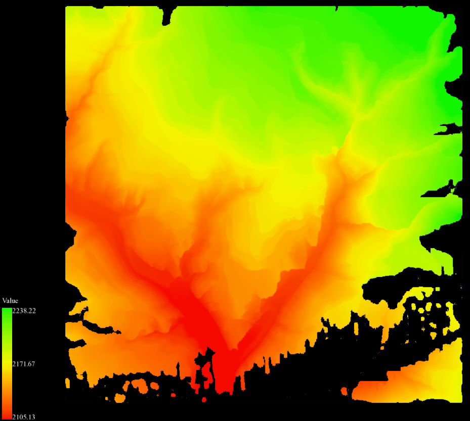
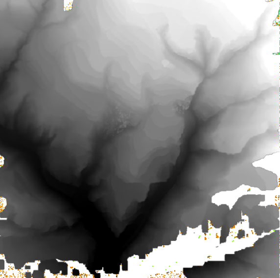
Digital Elevation Model (DEM) represents the ground elevation with a set of ordered numerical array. DEM can be created from LiDAR point cloud which has ground points classified.
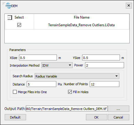
1 Go to Terrain > DEM. The point cloud that has ground points classified will appear in the tool’s input list. Set tool parameters as below and click OK to run the tool.
Interpolation Methods:
- IDW: When Inverse Distance Weighting (IDW) interpolation method is used, the assigned values to unknown points are calculated with a weighted average of the values available at the known points.
- Kriging: Kriging is a method of interpolation for which the interpolated values are modeled by a Gaussian process governed by prior covariances.
- TIN: TIN interpolation method extracts a grid cell value from a surface formed by a plurality of triangles consisting of the nearest adjacent point.

Parameters of DEM tool:
- XSize and YSize: Through XSize and YSize, users can set the size of sampling interval (resolution) in meters. This is also the pixel size of the output DEM raster.
- Merge files into one: when more than one file is selected as input, if this option is not checked, each point cloud data will be processed separately, resulting in more than one output DEM raster file. If this option is checked, the generated raster files would be merged into one file.
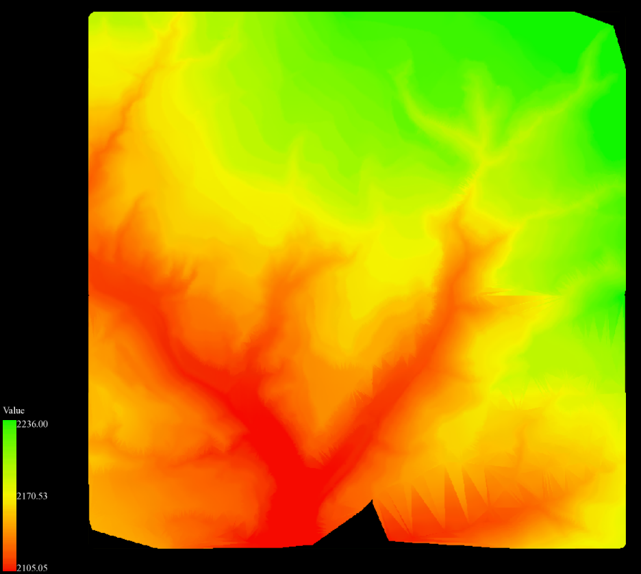
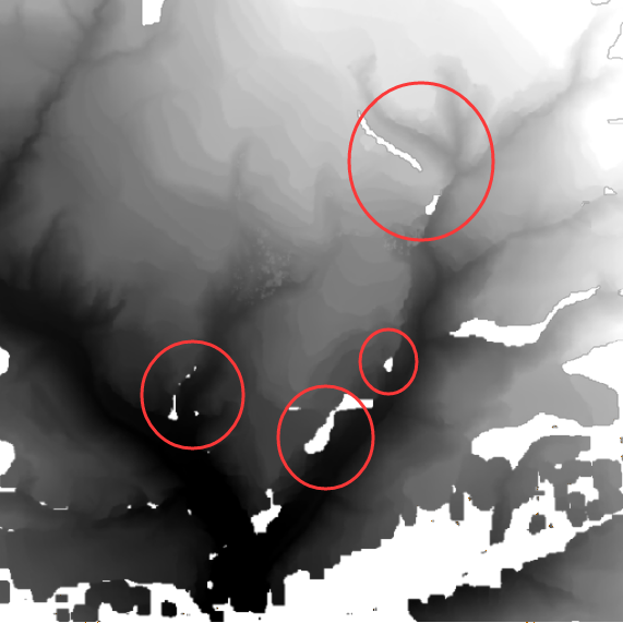
- Fill in holes: Missing data in the point cloud may result in holes in the DEM raster. Checking this option can fill in missing data with values interpolated based on neighbor values.
- Please refer to User Guide for detailed description of interpolation methods used in LiDAR360 and other parameters of the tool: Grid Parameters.
DSM (Digital Surface Model) Production
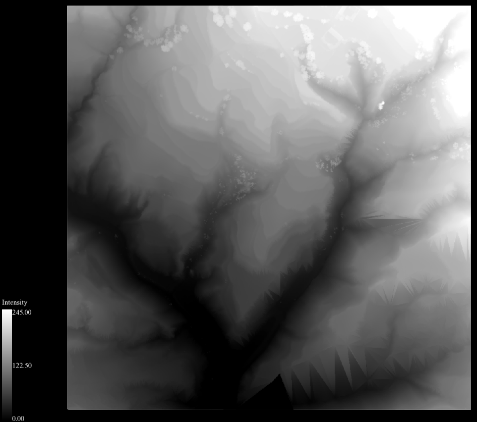
Digital Surface Model (DSM) refers to the digital representation of the terrain surface. Compared to DEM, DSM contains more elevation information for buildings, bridges, forests and other surface object that do not exist in the DEM.
2 Go to Terrain > DSM. In the following window, set From Class to Ground and UnClassified, Return Number to all returns, and Interpolation Method to TIN. In the TIN settings, choose Spike Free TIN, and set Freeze Distance to 1 (meter), Insertion Buffer to 0.5m, and everything else the same as in DEM in Section 1. Click OK to run the tool.
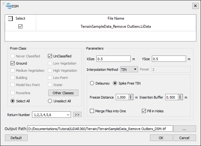
- Spike Free TIN: When this option is checked, the points with abnormal elevation are removed, in order to generate TIN without obvious spikes.
- Freeze Distance: The shortest distance in xy plane of each side of the triangle in the triangulated network. The larger this value is, the fewer points will be involved in creating the network, the smoother the network will be and the fewer surface details will be included in the output TIN.
- Insertion Buffer: Decreasing this value will result in fewer spikes, faster processing speeds, and less detail in the TIN result.
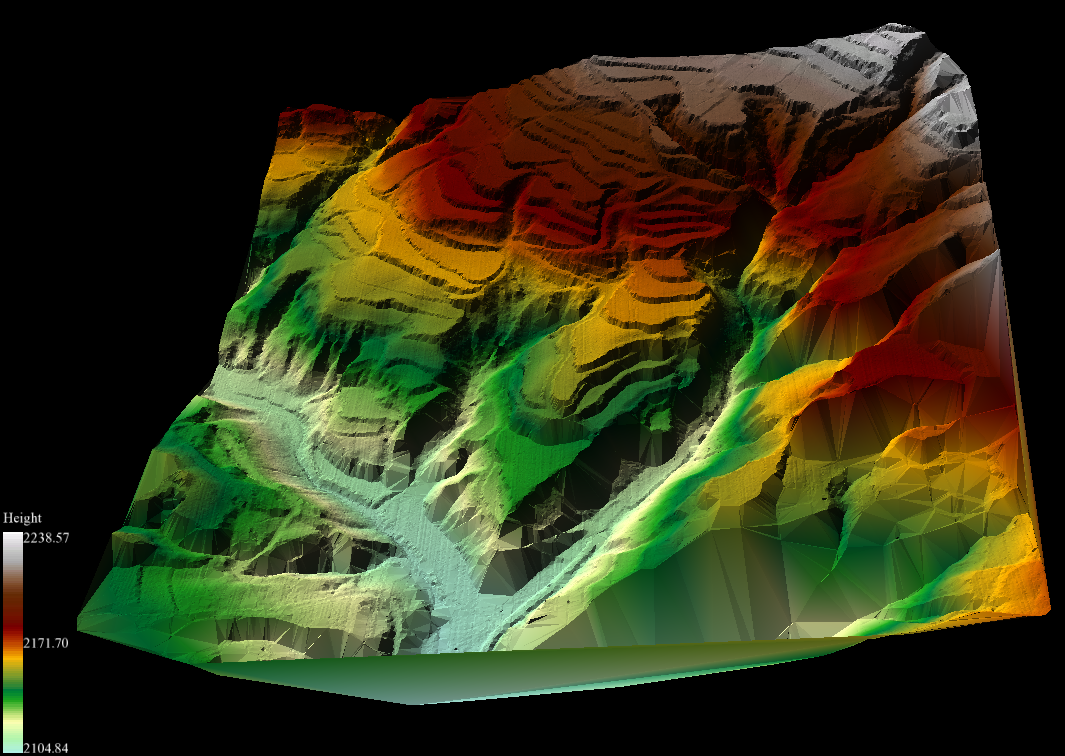
TIN Production
LiTin is a LiDAR360 custom triangulated irregular network (TIN) model file format. A LiTin model generated from a LiDAR point cloud can be edited to smooth irregular variation in point elevations as well as to add and remove network vertices. These tools give Terrain module users an ability to improve the quality of contour line and digital elevation products generated from the edited TIN model. Use the interactive classification tools and workflow introduced in Exercise 2 of this tutorial to re-classify these points into Building.
3 Go to Terrain > Generate TIN. In the following window, set From Class to Ground, Method to Spike Free TIN, Freeze Distance to 1.0m, Insertion Buffer to 0.5m, and click OK.
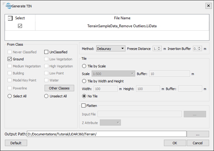
The resulting *.LiTin file will need to be manually added into the current LiDAR360 project.
The LiDAR360 viewer cannot be in 3D mode when there are raster data sets loaded in the viewer. Remove the raster layers in order to switch viewer mode from 2D to 3D.