How to: Acquire High-Accuracy GVI GNSS Base Station Locations Using a 3rd-party GNSS RTK/PPK Surveying System
GreenValley International’s (GVI) LiAir systems are able to generate LiDAR point clouds with high levels of accuracy. To achieve the highest levels of absolute accuracy for a given project, LiAir users are required input high-accuracy GVI Base Station location coordinates and elevation values rather than making use of functions in LiAcquire that allow them to auto calculate GNSS base station locations directly from the base station data collected during LiAir data acquisition.
In many instances the LiAir GNSS Base Station must be set up in areas where survey monuments are not yet in place or have not had their locations collected in reference to the WGS84 Geographic Coordinate System and its associated ellipsoid that important GVI software products require. When appropriate survey monument data is unavailable it is recommended that users acquire GNSS RTK/PPK location survey measurement points at LiAir Base Station setup locations.
This GVI How-To document will outline, in a very general way, the steps that must be taken to collect accurate base station location coordinates using a GNSS base-rover surveying system. Following recommended workflow steps as they have been laid out in this document, will allow LiAir users to accurately determine the locations of GVI GNSS Base Station set-ups. This document also describes the steps that must be taken to obtain important LiAcquire Pro (with LiNav) input values including antenna height. Please note that users should consult a professional surveyor when deploying GVI hardware and software products on projects where specific accuracy requirements must be met.
REQUIRED EQUIPMENT (* = Not sold by GVI)
GNSS Base-Rover RTK/PPK surveying system with receiver
GNSS rover antenna rod
Surveying tripod with tribrach and optical plummet
Surveying nail(s)
*Measuring tape (in meters)
GVI GNSS Base Station antenna, receiver, and antenna adaptor
RECOMMENDED WORKFLOW
STEP 1: MEASURE GVI GNSS BASE STATION SETUP LOCATION
1.1 Find an open area where there is good GNSS satellite coverage. The GVI GNSS Base Station should be set up within 10 km of the LiAir data collection site.
1.2 Install survey nail at the desired GVI Base Station set up location.
1.3 Power on the GNSS rover antenna and attach to top of the rover rod. Place the rover rod tip on the center of the surveying nail. Note that this workflow assumes user has the 3rd-party GNSS survey system’s base station set up and running or has plans to use a service like OPUS in the United States to do the PPK corrections on the GNSS measurement data.
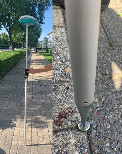
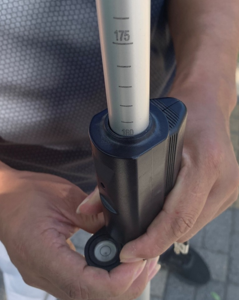
1.4 Level the receiver antenna and record the height of the GNSS rover rod. Please refer to the manufacturer’s GNSS Base-Rover RTK/PPK surveying system manual for more information on how to collect measurements with the third-party surveying equipment being used.
Typically, users must then enter the height of the rover rod as well as the model of the rover antenna into the GNSS surveying system’s handheld receiver before recording GNSS measurements that can be used to identify the coordinates of the surveying nail’s location (a.k,a the GVI GNSS Base Station location).
Note: GNSS coordinates collected by the user’s GNSS Base-Rover RTK/PPK surveying system must be in WGS84 Geographic Coordinate System (lat/long degrees) and the height (elevation) values must be in WGS84 Ellipsoid Height (meters) when they are to be used as inputs to the LiNav module in LiAcquire. Users can then use GVI reprojection tool found in LiDAR360 and LiAcquire to change point cloud coordinate values that reference the default WGS84 Geographic Coordinate System to another target spatial reference system. Please click here for detailed information on how to transform the coordinate system.
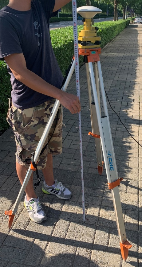
STEP 2: SET UP GVI BASE STATION ANTENNA AND RECIEVER
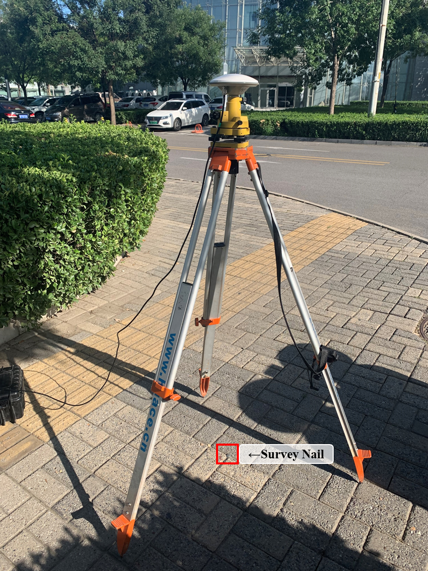
2.1 Setup surveying tripod with tribrach. Level tribrach while ensuring the tribrach’s center is horizontally aligned with the center of the surveying nail. Use the tribach’s optical plummet (if available) to make this portion of the workflow easier
2.2 Attach GVI GNSS Base Station antenna at the top of the tribrach
2.3 Connect GVI Base Station antenna and receiver with GVI provided cables
2.4 Power on the GVI Base Station and start logging data using the controls on the receiver
STEP 3: MEASURE GVI GNSS BASE STATION ANTENNA HEIGHT
3.1 Determine the distance from the bottom edge of the rubber ring on the GVI GNSS Base Station antenna to the center point of the survey nail. Use measuring tape find this distance to the nearest millimeter
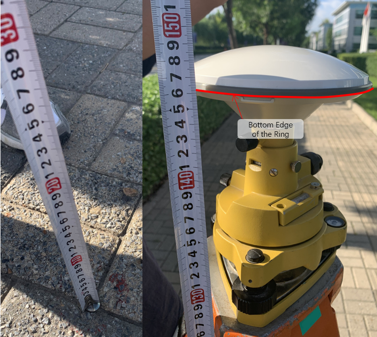
Note: In the proceeding images the distance between the bottom edge of the rubber ring and the center of the survey nail was recorded to be 1.462 meters.
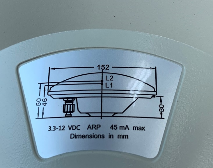
Note: The diagram above shown is located on the bottom side of the GVI Base Station GNSS antenna. It contains information need to calculate the true height of the GNSS antenna center of the center of the surveying nail. To determine the true height of the antenna above surveying nail, the surveyor must to account for the error introduced by taking a distance measurement from a point on the GNSS antenna horizontally offset from the center of the antenna (a.k.a. the point we want to measure to from the center of the surveying nail). This geometrical concept can be better understood by studying the figure below.

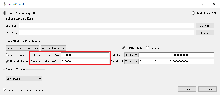
3.2. Do the math. Record the measured distance as d and the height above the ground of the GNSS antenna center as h (the value we are trying to obtain). The equation to find h when only d is known is:
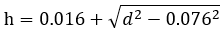
3.3. We would then enter this h value to the “Antenna Height” and the ellipsoid height measurement that was obtained from the GNSS RTK/PPK survey system deployed in STEP 1 of this recommended workflow to “Ellipsoid Height” when processing LiAir data in LiAcquire.