Subscribe

Generating Terrain Models using LiDAR360

-- 15 Dec 2021 --

a.png


This case combines LiDAR point cloud post-processing software LiDAR360 
and uses data collected from an open-pit mine as test data to introduce the application of 3D point cloud data in the production of terrain products.

Digital elevation model (DEM), digital surface model (DSM), digital terrain model (DTM), and contour lines are four commonly used geospatial features generated by UAV (drone) surveying and mapping systems. These products are very useful for landscape monitoring, such as terrain reconstruction, precision agriculture data analysis, landslide monitoring, and erosion assessment. In addition, LiDAR detection technology can collect data combined with remote sensing technology to provide three-dimensional (3D) data with high spatial and temporal resolution. This case combines LiDAR point cloud post-processing software LiDAR360 and uses data collected from a mountainous area as test data to introduce the application of 3D point cloud data in the production of terrain products.


1.      Topographic product concept

DEM (Digital Elevation Model) realizes the digital simulation of the ground terrain (that is, the digital expression of the terrain surface form) through limited terrain elevation data. It simulates the earth in the X, Y, and Z dimensions, and digitally defines the Z dimension of the terrain. Variety;

DSM (Digital Surface Model) is a digital representation of elevation in a regular grid cell structure, which represents all related natural and man-made entities' earth terrain changes;

DTM (Digital Terrain Model) looks like DSM, but it excludes all-natural and man-made objects to a certain extent. It uses algorithms to remove natural and man-made entities from DSM and only represents terrain, thereby generating DTM;

The contour line refers to the closed curve formed by adjacent points of equal elevation on the topographic map. A closed curve formed by connecting points with the same altitude on the ground and projected vertically onto a horizontal surface, and scaled-down on the drawing to obtain a contour line.

For the terrain production analysis of 3D point cloud data, here we only discuss DEM, DSM, and contour lines. DTM is often used in GIS and mapping.


2.      Production of terrain products

LiDAR is one of the most widely used technologies for obtaining point clouds to generate terrain products. Laser scanners are placed on satellites, airplanes/helicopters, ships/vehicles, or tripods. After the laser pulses are reflected by objects, the strength of the return signal provides information about the information of object characteristics is used to analyze point cloud data representing bare land, vegetation, water, or man-made ground feature infrastructure, for example. The analysis and application of point cloud data are often based on specific categories. The classified point cloud helps to analyze the objects of interest, speed up the calculation speed and reduce noise. For example, only if the vegetation points and ground points are classified first, the ground points can be used for interpolation to generate a continuous terrain surface without vegetation, that is, a digital terrain model (DTM). When removing the elevation (digital elevation model, DEM) from the vegetation surface (DSM, digital surface model), it can be used to estimate the vegetation height (canopy height model, CHM) and derivatives, such as total above-ground biomass. The first step in the production of terrain products, we first classify the data, and divide the data into ground point and non-ground point data.


Denoising

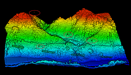
Before the ground point classification, we first need to check the data quality, remove the influence of isolated points and noise, and make the generated terrain products such as DEM and DSM closer to the real terrain shape. Denoising is to remove the influence of high-level gross errors and low-level gross errors. High-level gross errors are usually affected by flying objects (such as birds, airplanes, or floating foreign objects) that the airborne LiDAR system receives in the process of collecting data. The reflected signal of the object is recorded as the measured object target. The low error is caused by the multipath error in the measurement or the systematic error of the laser rangefinder. In this example, the noise is shown in Figure 1 below:  
download.png
Figure 1 Schematic diagram of noise points


For noise removal, each point in the point cloud can be analyzed, and the average distance to all neighboring points can be calculated separately. Assuming that the result is a Gaussian distribution, its shape average and standard deviation are determined, then the average distance is within the standard range Outliers can be defined as outliers and removed from the data.


Ground point classification

The technique of identifying ground points from 3D point clouds is usually called ground filtering or bare ground extraction. Many ground filtering methods have been developed over the years, especially for ALS point cloud data. Ground filtering methods usually use a certain discriminant function to classify ground points and off-sites. Behind each discriminant function is a model of assumptions or some attributes of the terrain (such as elevation, slope, curvature, etc.).

Among the many ground point filtering algorithms, it is well-known and the basis of the filtering algorithm is the Improved Progressive TIN Densification (IPTD) classification of ground points. This algorithm first generates a sparse triangulation network through seed points and then encrypts it layer by layer through iterative processing. Until all the ground points are classified, the specific steps of the algorithm are as follows:

1. Selection of initial seed point. In the point cloud data containing buildings, the maximum building size is measured as the grid size to grid the point cloud data. For the point cloud data without buildings, the default value is used as the grid size. Take the lowest point in the grid as the starting seed point.

2. Construct a triangulation network. Use the starting seed point to construct the initial triangulation.

3. Iterative encryption process. Traverse all the points to be classified, query the triangle in which the horizontal projection of each point falls, calculate the distance (d) from the point to the triangle and the maximum value of the angle between the three vertices of the point and the triangle and the plane where the triangle is located. The iteration distance is compared with the iteration angle. If it is less than the corresponding threshold, the point is judged as a ground point and added to the triangulation network. Repeat this process until all ground points are classified. The schematic diagram of the angle is shown in Figure 2 below:


Figure 2 Schematic diagram of angle for ground point classification


The algorithm flow is shown in Figure 3 below:


Figure 3 Algorithm flow chart


Generate DEM

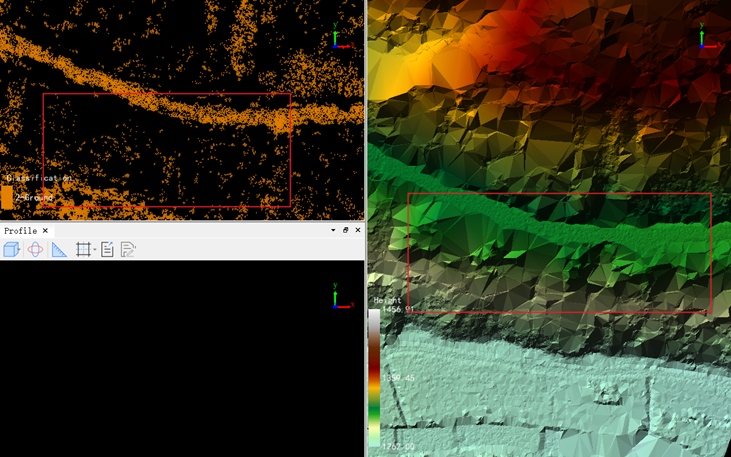
Given a three-dimensional point cloud, several factors affect the accuracy of DEM, such as the density and distribution of the point cloud, raster resolution, and the interpolation method used to generate the DEM. The three commonly used raster unit interpolation methods are: inverse distance Weight interpolation, Kriging interpolation, and irregular triangulation interpolation, in the inverse distance weight interpolation method, use nearby points to calculate the value of the grid unit, and judge the weighted average by the distance between the point and the center of the grid unit; Kerry The golden interpolation method calculates the optimized covariance, and uses Gaussian process to interpolate the grid value; irregular triangulation interpolation, extracts the grid unit value from the surface formed by multiple triangles composed of the nearest neighboring points. Based on these three different methods, DEM can be generated based on point cloud data. In addition, DEM can also be generated based on TIN. Based on DEM, products such as slope, aspect, roughness, and contour can be further calculated. Due to the influence of scanning equipment and scanning environment, point cloud data is often missing. Generating DEM based on point cloud or TIN will cause inconsistency with the real ground elevation model. At this time, you can import the fracture line to repair the missing terrain features. As shown in Figure 4 below, due to the data occlusion and the missing point cloud under the forest, the result of the TIN structure does not conform to the actual terrain conditions.

4.png

Figure 4 Hole causes TIN error situation


Generate DSM

DSM is based on DEM and further covers the elevation of other surface information except for the ground. Same as the DEM interpolation method, the DSM interpolation method can also choose inverse distance weight interpolation, kriging interpolation, and irregular triangulation interpolation. Based on the different methods of the irregular triangular network, the network can be constructed according to the two methods of Delaunay and TIN without pits.


Generate contour lines

Traditionally, contour lines can be generated by photogrammetry methods, but these methods have low production efficiency and data accuracy is not high enough in some areas, such as densely-vegetated forests, deserts, and coastal areas. Lidar detection technology (LiDAR) is applied because of its high accuracy, high efficiency, and relatively low cost in 3D spatial data acquisition, and is gradually used in the production of contour lines.

If the contour lines are extracted directly from the filtered point cloud, the obtained contour lines are prone to jag, which will damage the smoothness of the contour lines. Therefore, to generate a smoother contour line, a break line can be introduced. The main idea behind this method is to treat the middle break line as a constraint to overcome the distortion of the generated contour line. After the break lines are extracted, they are used as constraint vectors to build a constrained irregular triangle network, and then a smooth high-precision contour line can be generated by this method.


3.       LiDAR360 Solution

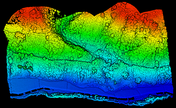
For noise removal, LiDAR360 provides noise removal tools. In addition, you can also choose to classify noise and air noise. By extracting point cloud tools by category, points other than noise can be extracted, and point cloud removal can also be achieved. Noisy, the result of LiDAR360 point cloud denoising is shown in Figure 5 below. It can be seen that all the high-level errors floating in the air have been eliminated:
5.png
Figure 5 Noise filtering results


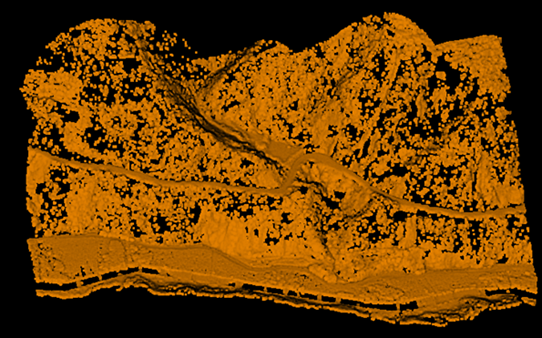
After the noise is filtered, the ground filtering result based on the progressive triangulation filtering algorithm is shown in Figure 6 below:
download.png

Figure 6 Ground point filtering results


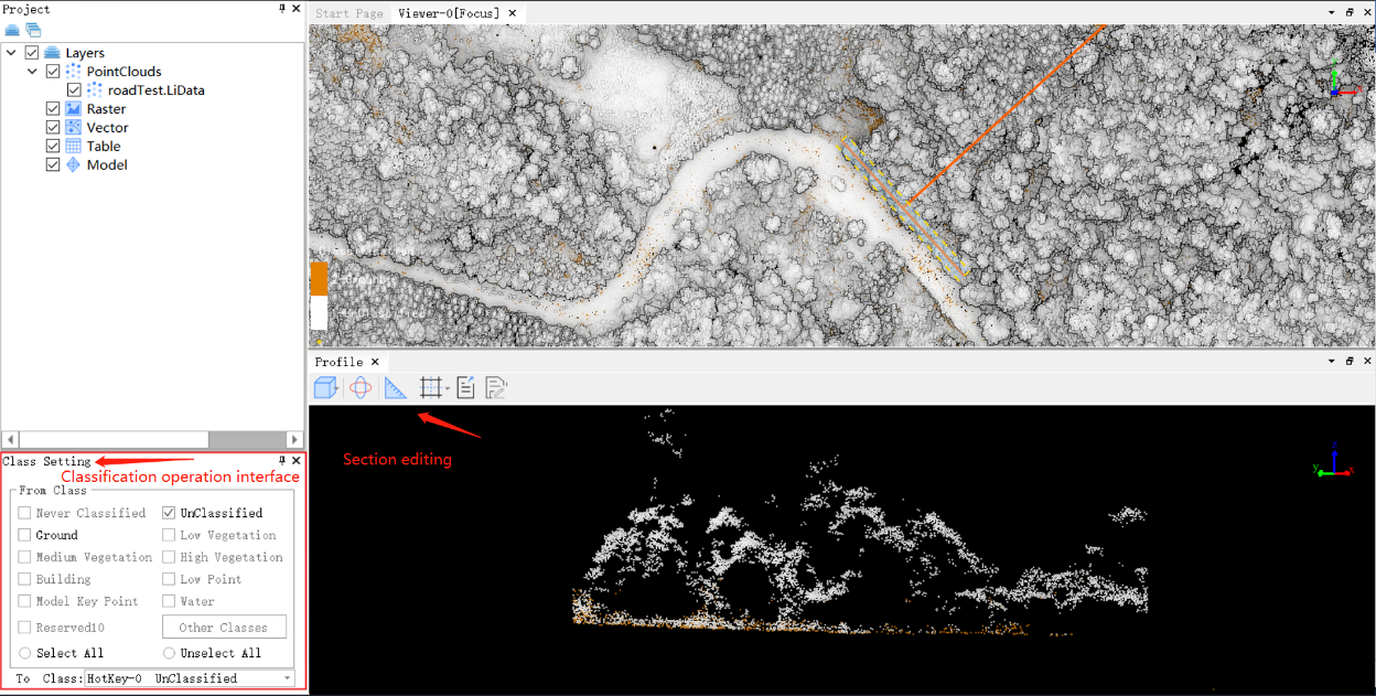
After the automatic classification of ground points, most of the ground points will have been classified. If you need to get more refined classification results, you must perform the section editing ground point classification. Section editing ground point classification can first divide the point cloud into several blocks, and then refine the classification steps to each block. Use the polygon selection tool to select the area to be edited, set the initial category and target category, and classify the unclassified point cloud or the point cloud that is misclassified into other features as ground points. This classification method is not only for ground points but also can set the target category as noise, water, vegetation, etc. to meet more needs. The operation interface is shown in Figure 7 below:
 7.png

Figure 7 Section editing and classification operation interface


After the ground point classification is completed, the point cloud missing holes caused by the scanning equipment or the occlusion of the cup will cause the TIN model to not conform to the actual topographic characteristics, and the generated DEM, DSM, etc. will have the problem of missing elevation. For the above terrain features, the LiDAR360 section editing tool provides a break line editing tool. You can insert a hard break line, view the TIN optimization result, and export the break line. Under the DEM tool, use this break line to optimize the model.

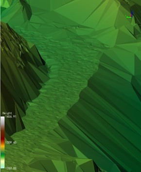
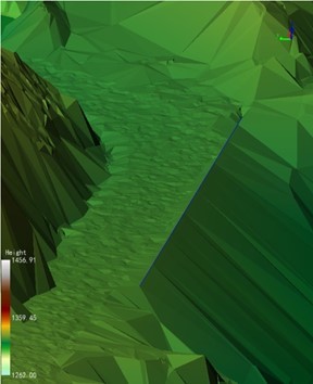
After the break line optimization, the result is shown in Figure 8 below. Figure 8 (left) is before adding the break line, and Figure 8 (right) is after adding the break line:
 

82.jpg


Figure 8 Schematic diagram of adding a break line


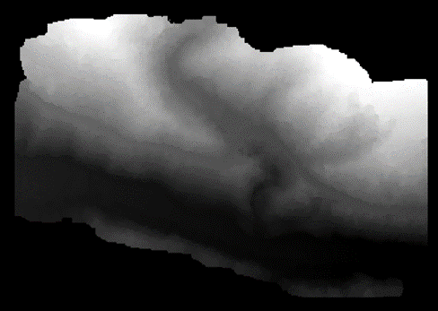
The final result of DEM generated after optimization of the fracture line is shown in Figure 9 below:
 

9.png

Figure 9 Generate DEM results


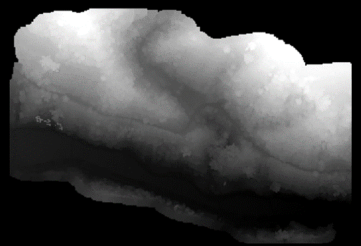
After the DEM is generated, the DSM result is generated based on the inverse distance weight difference method as shown in Figure 10 below:
 10.png

Figure 10 Generate DSM results

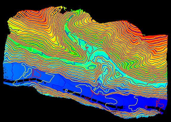
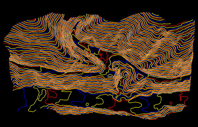
LiDAR360 can generate contour lines based on point cloud and TIN data. At the same time, it can import break lines to generate smooth contour lines. The contour line result is shown in Figure 11 below, and Figure 11 (left) shows the contour superimposed point cloud data. As a result, Figure 11 (right) is the contour line:

112.png 

Figure 11 Contour line generation results


 Summary

Lidar detection technology has become one of the largest contributors to the production of usable and accurate terrain products because its standard data product is a geolocation point cloud with centimeter-level horizontal and vertical accuracy. These geospatial data provide more data information than two-dimensional data and promote the development of the entire industry including topographic mapping, forestry resource survey, mining survey, power inspection, disaster analysis, etc. LiDAR360 has been committed to promoting the entire LiDAR industry and solving the user's every application problem.


Recommended Articles

HOW CAN WE HELP YOU?
Message us your questions and contact information.
We’ll get back to you right away!