Frequently Asked Questions for LiDAR360
What are the hardware requirements and supported operating systems for LiDAR360?
RAM: at least 8G or more.
CPU: Intel® Core™ i5/i7; Dual-core processor.
Display Adapter: NVIDIA graphics card recommended, video memory no less than 2GB.
Operating Systems: Windows 7 (64 bit), Windows 8 (64 bit), Windows 10 (64 bit) or Windows Server 2012 or later.
After successful installation of LiDAR360 on my computer, why does the software crash when I try to open or load data in the program?
Please check whether the software installation environment satisfies the recommended hardware configuration. If yes, please check the following two things. (1) Whether the graphic card is working properly. Right click on My Computer, select the device manager, find the corresponding graphic card in the Display Adapter, and view the graphic card property status. If it shows "this device is working normally", it means that the graphic card device is running properly. (2) Update the graphic card driver to the latest version, and then use the high-performance graphic mode to run the software. For the operating procedure, see adjust the graphics mode to high performance.
Please contact us by email info@greenvalleyintl.com for further assistance if the problem persists after confirming that your computer satisfied our minimum system requirement and the GPU on your computer is working properly with up-to-date drivers installed.
Why does LiDAR360 display a message indicating the trial license key has not loaded or failed to open?
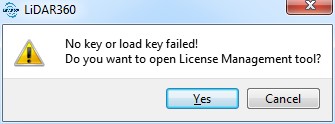
- The LiDAR360 trial license key may fail to load for the following reasons:
- System Time Changes: If the system time changes during the trial period, the trial period may expire prematurely.
- Trial Expiration: LiDAR360 has a 30-day trial period for each version. If the same version has been installed for 30 days, the trial will be expired.
- Other Reasons: Please contact us by email info@greenvalleyintl.com, if further assistance is needed in troubleshooting issues related to trial license keys.
How do I activate LiDAR360?
- Step 1:
- Send Activation Information: Run the software as administrator, click Help > Activate License in the menu bar, or double-click the License Manager.exe in the installation directory.
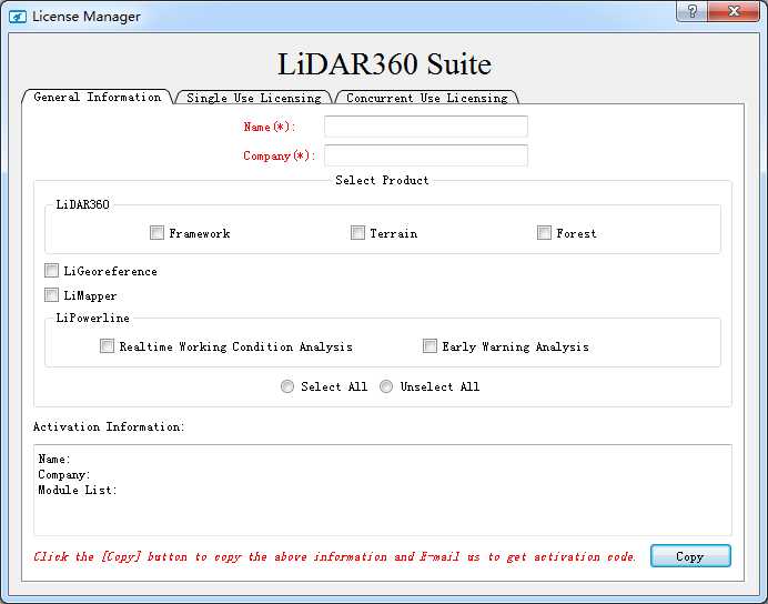
- Fill in Name (Mandatory);
- Fill in Company (Mandatory);
- Select the appropriate module(s);
- Click Copy;
- Send an email with the copied content to info@greenvalleyintl.com.
- Send Activation Information: Run the software as administrator, click Help > Activate License in the menu bar, or double-click the License Manager.exe in the installation directory.
- Step 2:
- Activate License (Single-Use): Copy the license code that you receive from GreenValley International and paste it in the “Key” field. Press ACTIVATE and a message should appear confirming that the activation was successful. Please refer to the License Manager Guide for more detailed license activation instructions or for information on how to activate a single-use license key in offline mode.
- Activate License (Concurrent-Use): Please refer to the License Manager Guide for information on how to activate a Concurrent-Use license key.
Does LiDAR360 support Windows Server System?
- Windows Server is supported.
- Please install and activate LiDAR360 using the administrator account. The software must be installed in a folder that all users can access to.
Can I continue to use LiDAR360 after the trial period ends?
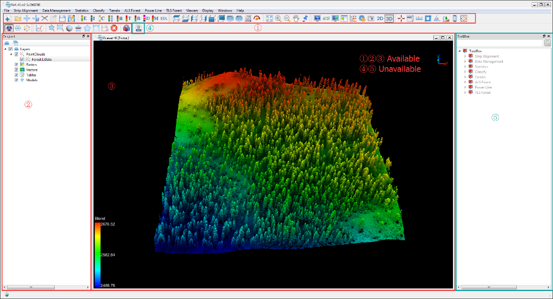
- When the trial period ends, you can still use the LiDAR360 software as a point cloud visualization tool. The major software functions, such as the viewer, measurement tool and selection tool in the toolbar, will still be available. If you need a license that will allow you to access all of the software’s functionalities or a license for a specific module, please contact us info@greenvalleyintl.com for more information on purchasing.
Why cannot the help document in the License Manager window be opened by clicking the help button?
- Please check if you have set a default program for opening PDFs. If not, please choose one and retry opening the help document in the License Manager window.
How can I use the authorization code on another computer if it cannot be revoked from the computer that it is currently activated on (e.g. if the computer with the active license on is broken or missing)?
- Please email info@greenvalleyintl.com with a brief description of the issue and the corresponding authorization code that needs to be revoked. We will then revoke the code in the activation server so that it can be used on another computer.
How to check to see which version of the LiDAR360 software is installed on my computer?
- You can check the version information of LiDAR360 in Help > About. In the screenshot below, 3.1 is the software version and Mar 4 2019 is the build date.

How can I change the display language of the LiDAR360 user interface?
- Navigate to Display > Language in the menu bar. English, Chinese and French are currently available.
What may cause the abnormal exit of the software?
- There are two known reasons for the abnormal software exits (aka crashes). The first cause is insufficient disk space or memory space on your computer. Please see the hardware requirements for running LiDAR360. The second known cause relates to having an instance of screen word capturing software (Youdao dictionary, etc.) running simultaneously. If you meet any other scenarios that lead to abnormal exits, please contact us at info@greenvalleyintl.com.
What are data types and file formats can be imported to and exported from LiDAR360?
- LiDAR360 can import the following data types and file formats:
- Point Cloud: Proprietary LiData File(.LiData), LAS file (.las,.laz), ASCII file (.txt, .asc, .neu, .xyz, .pts, .csv), PLY file (.ply).
- Raster: Image file (.tif,.jpg).
- Vector: Shapefile (*.shp).
- Table: Comma separated value file (*.csv)
- Model: Proprietary 3D object file (.LiModel), Proprietary TIN File (.LiTin), OSG model file types(.osgb, .ive, .desc, .obj).
- LiDAR360 can export the following data types and file formats:
- Point Cloud: Proprietary LiData file (.LiData), LAS file (.las,.laz), ASCII file (.txt, .asc, .neu, .xyz, .pts, .csv), PLY file (.ply).
- Raster: Image file (.tif,.jpg).
- Vector: Vector type file (.shp, .dxf)
- Table: Comma separated value file (*.csv)
- Model: Proprietary 3D object file (.LiModel), Proprietary TIN File (.LiTin).
How can I fix an incorrect color scheme display?
First, right-click on the desktop and select NVIDIA Control Panel.
Second, select manage 3D settings > program settings > add to add the LiDAR360.exe to the list of high-performance graphics mode programs. For more information on this topic, please refer to the LiDAR360 User Guide’s section on how to adjust high-performance graphics mode.
What should I do if I cannot open files by dragging and dropping files into LiDAR 360 window?
First, right click on the Windows Start Icon and select RUN. You can also search for "regedit.exe" then run the executable as an administrator.
Then, on Registry Editor go to: HKEY_LOCAL_MACHINE\SOFTWARE\Microsoft\Windows\CurrentVersion\Policies\System and double click "EnableLUA"
Next, change the value from 1 to 0.
Finally. Restart Windows and the problem should be solved.
For more information on this topic please refer to Reference.
Why is the EDL visual effect not obvious if multiple data are added in the same window?
- If several data sets distant from each other are in the same window, the EDL rendering effect will be very unobvious. You can open the data sets in different windows.
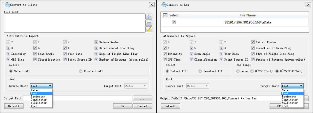
What is the default display and measurement unit of point cloud data in LiDAR360? What should I do if my data is in imperial units of measurement (such as US Survey foot)?
- The default unit is meter. If you have point clouds with foot or other units, they can be converted by Data Management > Conversion > Convert to LiData / Convert to Las.
Is LiDAR360 capable to handle point clouds generated by photogrammetry software?
- Yes, point clouds generated from photogrammetric software (aka PhoDAR point clouds) can be imported to LiDAR360 as .las, .laz, .ply, and various .ascii formatted files.
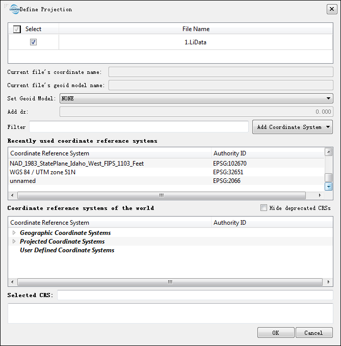
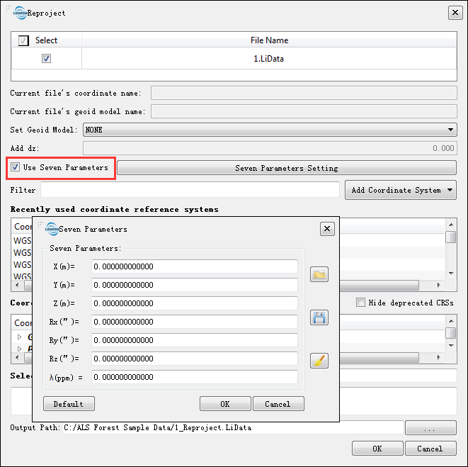
How can I use LiDAR360 to perform seven parameter transformations?
Click Data Management > Projections and Transformations > Reproject.
Check Use Seven Parameters.
Input seven parameters: translations X, Y, Z; rotations Rx, Ry, Rz; and scale λ.
Select target coordinate reference system. (Note that you may also have to define projection for the point cloud if it doesn't have source coordinate reference system assigned to it yet.)
How can I subsample the point cloud uniformly?
LiDAR360 provides multiple subsampling methods including Minimum Points Spacing, Sampling Rate, and Octree. The subsampling by Octree is a uniform method.
Click Data Management > Point Cloud Tools > Subsampling, then select the sampling type Octree.
How can I change the Rotation Center while using the Pick Multi-Point tool?
- Hold the Ctrl key and left-click mouse button while pointing to the location where you want the center of rotation to lie.
What unit of angle measurement is used for point cloud transformation in LiDAR 360?
- The unit of angle measurement used in LiDAR 360 is degree rather than radian.
Can LiDAR360 outputs be used as inputs to common GIS software platforms like ESRI ArcGIS or QGIS?
- Yes. LiDAR360 can export point clouds and other data products as shapefiles (.shp) or raster (.tiff) files which can be easily brought into common GIS programs. LiDAR360’s toolsets can also be used to create polygons, polylines, point vector files. It can also produce a variety of digital elevation products (e.g. DEMs, DSMs, nDSMs or CHMS, etc.) and export them in GIS friendly file formats.
What physical memory (RAM) requirements must be met in order to process large datasets in LiDAR360?
- We recommend at least 16 GB of RAM for processing large datasets.
How can I fix very large errors observed in the outputs of the manual registration tool?
- Remove the co-located points pairs (aka homologous points) with the largest residual errors between them. After removing the pairs with the greatest residuals, or picking new co-located point pairs, rerun the transformation function included in the manual registration tool. Inspect the result to confirm that the error has been reduced or eliminated.
What trajectory file formats are currently supported by LiDAR360?
- ASCII format (.pos) and binary format (.out) are currently supported.
- *.pos file contains GPS time, longitude and latitude (or geographic coordinates in X and Y), flight height, roll, pitch and heading. An example is shown as follows:
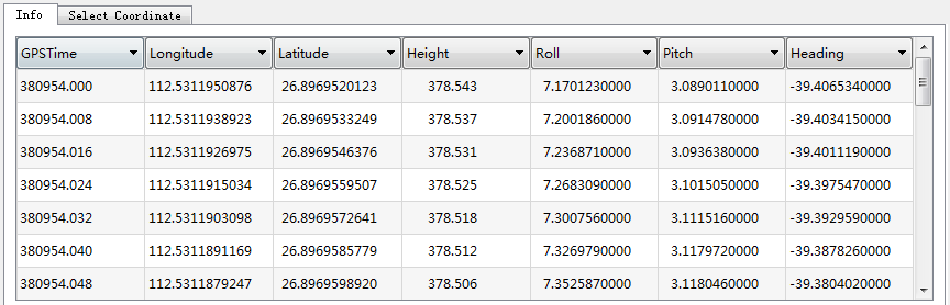
- *.out file is a proprietary format of the company Applanix. Please refer to OUT File for more information.
- *.pos file contains GPS time, longitude and latitude (or geographic coordinates in X and Y), flight height, roll, pitch and heading. An example is shown as follows:
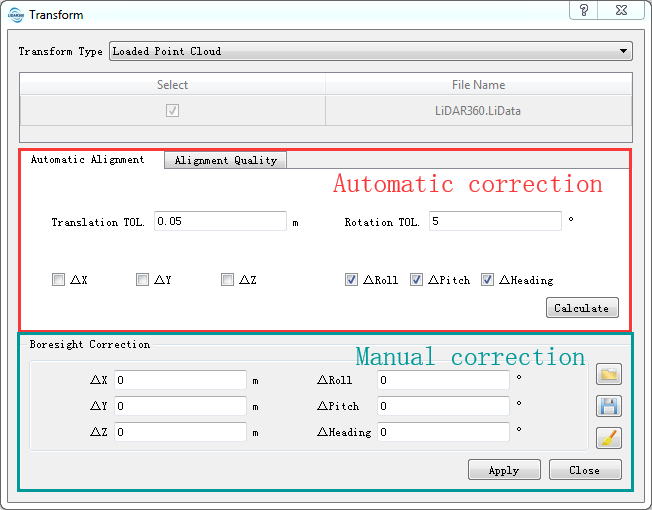
Does the strip alignment tool in LiDAR360 allow for manual and automatic finding of boresight correction (alignment) values?
- There are both manual and automatic methods for determining boresight correction (alignment) values in LiDAR360.
What trajectory file and point cloud file time stamp formats and types are supported by LiDAR360’s Strip Alignment Tool? Is it necessary to use GPS Time formatted stamps?
- The only requirement is that the time stamps in trajectory file (e.g. .pos file) and point cloud data (e.g. .las or .LiData files) are of *the same time reference system (e.g., GPS Time or UTC Time). If they are not of the same systems, you will need to convert one to match the other. Generally, point cloud time stamps are recorded in SOW (seconds of a week) or SOD (seconds of a day) formats.
Sometimes, after the strip alignment tool has been run, ALS point cloud strips will only be partially aligned or distorted in areas. Why does this occur?
- Poor strip alignments and point cloud distortions may occur if the trajectory file is of low accuracy. The principle of the Strip Alignment tool is to correct boresight errors between laser scanner system and GPS/INS system. The precondition is that the trajectory file’s accuracy for the ALS acquired dataset meets standard specifications. If this precondition is not met, the resulting point clouds are likely to be fully or partially distorted. Boresight correction alone doesn't guarantee the aligned results with high accuracy, trajectories must also be highly accurate for the strip alignment tool to produce high quality results.
Why there is no output when I try to clip the point cloud data with the trajectory file?
- Please check the GPS start and end times for both the input trajectory file and point cloud file. There must be time overlap between the time stamps of the two files for the Strip Alignment tool’s clip function to work. Also, check to see that the time stamp formats are the same for both inputs.
What ground points filtering algorithm is used in “Classify Toolbox” of LiDAR360 software?
- LiDAR360 makes use of an Improved Progressive TIN Densification (Zhao et al.,2016) filtering algorithm to classify ground points. For more information on specific parameter settings see "Classify Ground Points" in the LiDAR 360 User Manual.
If the LiDAR point density is much larger than the DEM point density requirement of the project, how should the original point cloud dataset be subsampled?
- If the LiDAR point density is much greater than the DEM-creation project required, you should turn to the Subsampling tool and subsample the original point clouds. This function provides three types of subsampling methods: "Minimum Points Spacing", "Sampling Rate" and "Octree".
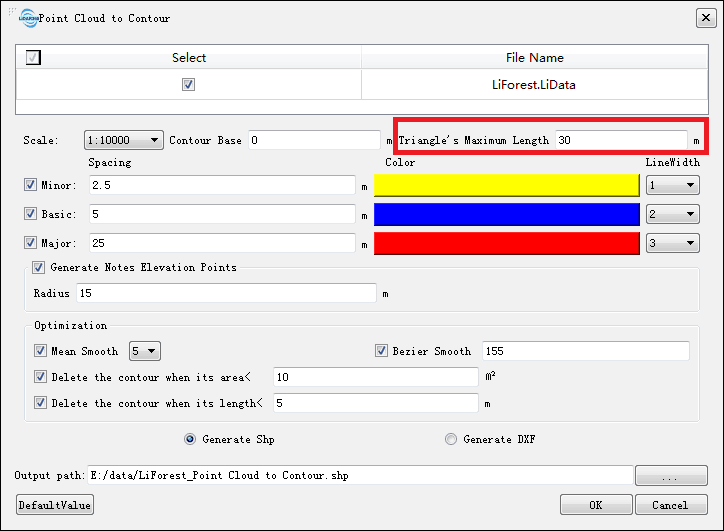
Some of the contour lines generated by the function "Point Cloud to Contour" are broken. Why?
- Broken contour lines may be caused by the lack of ground points. The contours can be made continuous by increasing the tool parameter "Triangle's Maximum Length".
How can I convert the .tiff formatted DEM file created with LiDAR360’s Terrain Module from a 2D to a 3D data type?
- You can convert a 2D .tiff DEM into GreenValley International’s custom 3D model format (LiModel). Go to Data Management > Conversion > Convert TIFF to LiModel. LiModel files can then be loaded into a 3D LiDAR360 Viewer for further inspection and use.
How can I check and improve the quality of DEM generated with LiDAR360?
- One approach to analyze the quality of the DEM created in LiDAR360 is to generate a hillshade map using the hillshade tool in the LiDAR360’s Terrain Module. At the same time, you can employ Data Management > Conversion > Convert TIFF to LiModel to convert single-banded Tiff images, like DEMs and hillshade maps, to LiModel objects. The benefit of LiModels is that 2D information types can be viewed in 3D; which is a more intuitive way to assess the quality of the 2D elevation products. The 3D LiModel can also be edited with the Terrain > LiModel Editor tool. This tool allows you to perform a variety of object-editing operations such as "Flatten Height", "Smooth Height", and "Repair Height". The improved elevation product can then be easily converted back into Tiff file for delivery. Similarly, DSM or CHM data can also be inspected and operated on as was described above for working with DEM elevation products.
How can I increase the smoothness of contour lines generated from a DEM in LiDAR 360?
- Smooth contours can be created from a DEM by first converting the DEM to a LiModel and then applying the smooth height tool (on the LiModel editing bar) to it. Next, convert the smoothed LiModel back to Tiff file format using Data Management > Conversion > Convert LiModel to TIFF. Lastly, derive contours from the height-smoothed DEM/LiModel using the Terrain > Raster to Contour tool.
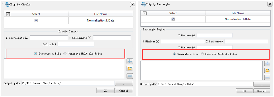
Is it possible to save the results of the clip by circle or clip by rectangle tool to a single file? Can each result be saved to a separate file when multiple clipping circles or polygons are used?
- The results of Clip by Circle and Clip by Rectangle can be saved as multiple files or merged into a single file. The user can choose how the point cloud outputs are saved when setting the parameters of either tool.
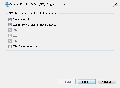
Can LiDAR360 generate canopy height models (CHM) in batch mode?
- LiDAR360’s batch processing capabilities can be used to generate CHMs. This functionality can be accessed by navigating to ALS Forest > Batch Process > Canopy Height Model(CHM) Segmentation. Users can also opt to include important data processing functions including outlier removal and/or ground point classification in the workflow to be batch processed.
How can I evaluate the accuracy of individual tree segmentation tool results?
- For an in-depth understanding of methods used to evaluate the accuracy of LiDAR360’s individual tree segmentation tools, please refer to Li et al's article on (Li et al., 2012). By comparing the outputs with field measurement data, users can determine the number of correctly segmented trees and the number of falsely segmented trees. The total number of missed trees can then be determined with the following approach and formulae. Users must first calculate recall (r), which indicates the ratio of detected trees that are correct, and precision (p), which indicates the ratio of trees in reality that are detected. The r and p values can then be used to find the F-score (F), which is a measure of the segmentation tool’s overall accuracy. The values of r, p and F all vary from 0 to 1.


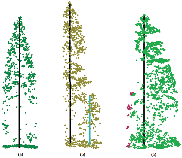
(a) Correctly detected tree (True Positive, TP) (b) undetected tree (False Negative, FN) (c) falsely detected tree (False Positive, FP)
What parameters affect the accuracy of canopy height model (CHM) segmentation results? How should I determine the tool parameter values?
- The accuracy of CHM segmentation tool results are affected by both the CHM resolution and Gaussian smoothing factor.
- CHM is the difference between DSM and DEM. The CHM resolution is determined by the resolution of DSM and DEM. Generally speaking, the CHM resolution value should not exceed one-third of the crown width, and the range can be set to 0.3-1.0 m. Usually, setting the CHM resolution of 0.5-0.6 m will yield results with higher accuracy. Moreover, the resolution of CHM should also refer to the point density of the point cloud.
- The Gaussian smoothing factor, Sigma, has a default value of 1. The larger the Sigma value is, the smoother the results. The degree of smoothness can affect the number of trees segmented out of the input point cloud. When the tool under-segments the input data, it is recommended to reduce the Sigma value (e.g. from 1.0 to 0.5); and in the case of over-segmentation, it is recommended to increase the value (e.g. 1.5).
- The CHM segmentation result can also be severely influenced by tree density and tree species. If the algorithm does not work well in certain forest types and structures, you can try to use other segmentation algorithms available in LiDAR360 to get the best segmentation result.
How can I remove individual trees that have relatively small crown areas after the CHM segmentation tool has finished running?
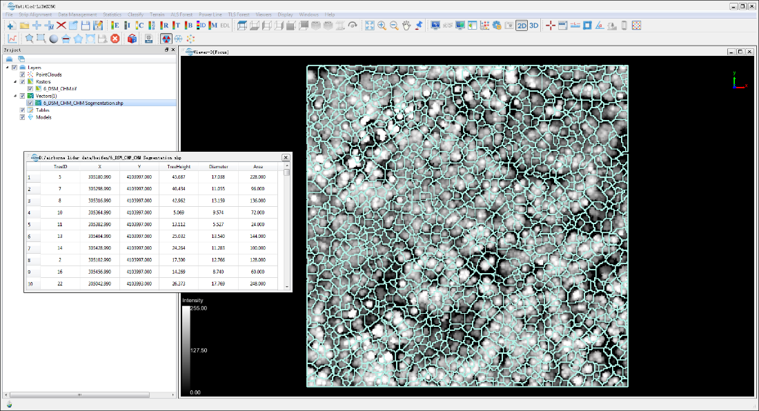
- After running CHM segmentation a shapefile (*.shp) containing the individual tree boundaries can be obtained. The attribute table for each polygon feature included in the output shapefile contains the ID, location, height, crown diameter and crown area of each tree. The shapefile can then be imported into a third-party GIS software (e.g. ESRI ArcGIS, QGIS, or Google Earth) where users can remove the individual tree records (attribute table rows) that have crown (which is shown in the figure below) areas that are too small to meet some user defined selection criteria.
How to can I include point cloud data within 2 m of the ground points in the LiDAR360’s segmentation routines?
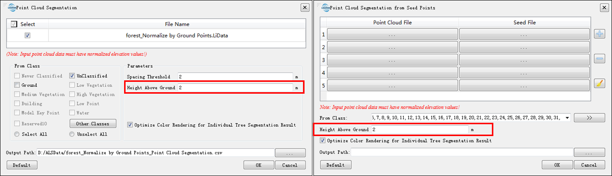
- The parameter "Height Above Ground" has been included in both the Point Cloud Segmentation and Point Cloud Segmentation from Seed Points tool parameters. You are able to use this setting to keep points below the 2 meters (default) high from being considered as an individual (or part of it) tree during the segmentation process.
Which segmentation method included in LiDAR360 is recommended when working with data collected in coniferous forest types versus data obtained from broad-leaved or mixed forest coverage types?
- For coniferous or broad-leaved mixed forest data, CHM Segmentation is recommended.
If the growth of trees in the area is not the same, how to achieve a higher segmentation accuracy?
- It is recommended to clip the point cloud according to the growth as different data by Select Tools or Clip Tools and handle them separately.
How can I export the results of the individual tree segmentation tools and bring them into a third-party software for additional processing or analysis?
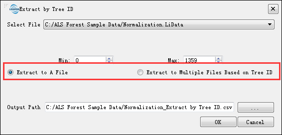
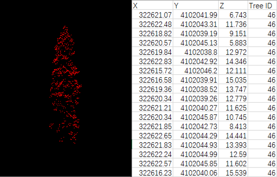
- Click ALS (or TSL) Forest > Extract by Tree ID, the segmented point cloud can be exported to CSV file for subsequent analysis using other software. LiDAR360 supports exporting each tree as a separate CSV file or exporting all points as one file. The exported CSV file is shown in the figure below, which contains X, Y, Z coordinates and tree ID information.
How many samples are required for regression analysis to yield an accurate estimate?
- The sample size for data used for regression analysis is not clearly defined. In general, under the premise of ensuring the accuracy of plot location and measurement, the greater the number of sample data is, the higher the accuracy of regression analysis can achieve. Sample sites should be randomly selected and representative to cover different forest types within the study area. A sample size less than 30 is referred as a small sample, and a sample size of 30 or greater is referred as a large sample. To ensure regression analysis accuracy, the recommended sample size should be greater than or equal to 30 (you should also consider the size and complexity of the study area).
How should I select the independent variables when running LiDAR360 regression analysis tools?
- The elevation percentiles obtained from LiDAR data are generally the independent variables for regression analysis. However, specific elevation percentiles are not all the same for different study areas.
How can I re-use trained regression models generated in LiDAR 360?
- Click ALS Forest > Regression Analysis > Run Existing Regression Model. All of LiDAR360’s regression models (Linear Regression, Support Vector Machine, Fast Artificial Neural Network and Random Forest Regression) can be used to estimate forest metrics.
Can I export the independent variables (e.g. elevation percentiles) generated by LiDAR360 into third-party software (e.g. SPSS, R) for regression analysis?
- Yes. Independent variables provided by LiDAR360 including Elevation Percentile, Elevation Density, Intensity Percentile, Leaf Area Index, Canopy Cover and Gap Fraction can be exported in highly transferable file formats. Among the metrics that can be exported, Elevation Percentile, Elevation Density and Intensity Percentile can be saved in CSV formats and then imported into third-party software such as SPSS directly. Leaf Area Index, Canopy Cover, and Gap Fraction are generated in TIF file formats that can be converted to text format by ArcGIS and then imported into third-party software.